
Experimental device for measuring diffusion coefficient of CO2 in oil reservoir

A diffusion coefficient and experimental device technology, applied in the field of petrochemical industry, can solve the problems of low generalization, error of measurement results, poor applicability, etc., and achieve the effect of high generalization, reduction of measurement error and strong applicability

Pending Publication Date: 2020-09-25
CHANGZHOU UNIV
View PDF9 Cites 0 Cited by
  • Summary
  • Abstract
  • Description
  • Claims
  • Application Information

AI Technical Summary

Problems solved by technology

In this way, during the sampling process, the CO 2 The concentration has a certain influence, resulting in errors in the measurement results
In some technical solutions, in order to solve the error problem during sampling, the experimental device of the sampling chamber was designed and canceled, and the pressure change method was used to obtain CO 2 diffusion coefficient, but the volume of the simulated reservoir in this experimental device is too small, and the general pressure sensor cannot accurately measure the change of pressure
Moreover, this device can only measure specific reservoirs, and physical parameters such as reservoir permeability and oil saturation cannot be quantitatively set, so the applicability is poor and the generalization is not high

Method used


Image

  • Experimental device for measuring diffusion coefficient of CO2 in oil reservoir
  • Experimental device for measuring diffusion coefficient of CO2 in oil reservoir
  • Experimental device for measuring diffusion coefficient of CO2 in oil reservoir

Examples


Embodiment Construction

[0017] The present invention is described in further detail now in conjunction with accompanying drawing. These drawings are all simplified schematic diagrams, which only illustrate the basic structure of the present invention in a schematic manner, so they only show the configurations related to the present invention.

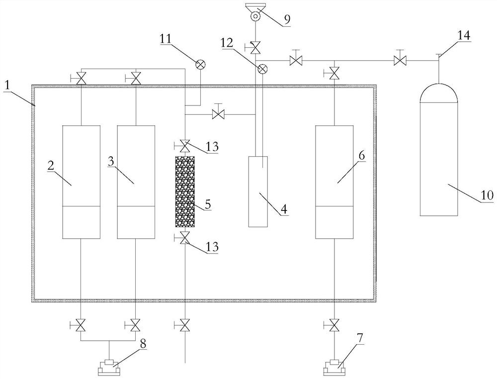
[0018] Such as figure 1 The one shown for measuring CO 2 The experimental device for the diffusion coefficient in the oil reservoir includes a constant temperature box 1, which has the functions of constant temperature, heat preservation and temperature record collection. The mineralized water tank 2, the crude oil tank 3, and the CO2 are vertically arranged in the constant temperature box 1. 2 Gas tank 6, gas chamber 4 and simulated oil reservoir chamber 5, the gas chamber 4 and oil reservoir chamber 5 are equal in volume; a first plunger pump 8, a second plunger pump 7, a CO 2 Gas cylinder 10 and vacuum pump 9.

[0019] The first plunger pump 8 is connect...


PUM


Abstract

The invention relates to an experimental device for measuring the diffusion coefficient of CO2 in an oil reservoir, and the device is provided with a constant-temperature box; a mineralized water tank, a crude oil tank, a CO2 gas tank, a gas chamber and a simulated oil reservoir chamber are arranged in the constant-temperature box, and the volume of the gas chamber is equal to that of the oil reservoir chamber; a first plunger pump, a second plunger pump, a CO2 gas cylinder and a vacuum pump are arranged outside the constant-temperature box; the first plunger pump is respectively connected with bottom pipelines of the mineralized water tank and the crude oil tank; the second plunger pump is connected with a bottom pipeline of the CO2 gas tank; the CO2 gas cylinder is respectively connectedwith the CO2 gas tank and a top pipeline of the gas chamber; the vacuum pump is respectively connected with the gas chamber, the simulated oil reservoir chamber and a top pipeline of the CO2 gas tank. By adopting the method for measuring the pressure change of the gas chamber, the diffusion coefficient of CO2 in the oil reservoir is calculated, the measurement error is reduced, the porosity, permeability, oil saturation and the like of the oil reservoir can be quantitatively set, the flowing condition of CO2 in the actual oil reservoir can be more effectively and truly simulated, the applicability is high, and the popularization performance is high.

Description

technical field [0001] The invention relates to the field of petrochemical technology, especially a method for measuring CO 2 Experimental setup for diffusion coefficients in oil reservoirs. Background technique [0002] CO 2 It can realize the volume expansion of crude oil through dissolution and diffusion, reduce the viscosity of crude oil, and improve the fluidity of crude oil. It is a good oil displacement gas. in CO 2 In huff and puff recovery technology, CO 2 The diffusion coefficient in the reservoir is an important factor affecting production parameters such as soaking time and gas injection rate. [0003] Currently common measurement of CO 2 In the device for simulating the diffusion coefficient in the reservoir, the sampling method is mainly used to measure the CO at both ends of the reservoir in real time through chromatographic analysis. 2 concentration change to calculate the CO 2 The diffusion coefficient. In this way, during the sampling process, the C...

Claims


Application Information

Patent Timeline
IPC IPC(8): G01N13/00
CPCG01N13/00G01N2013/003
Inventor 陶磊黄森袁潇程浩张娜李兆敏李宾飞汪城李进龙
Owner CHANGZHOU UNIV
Learn More