
Neural signal amplifier based on MTJ device

A neural signal and amplifier technology, applied in amplifiers, DC-coupled DC amplifiers, push-pull amplifiers, etc., can solve the problem that neural front-end amplifiers cannot effectively identify and amplify action potentials below 300Hz, and achieve the effect of reducing occupancy

Pending Publication Date: 2020-09-25
南京明尼晶磁电子科技有限公司
View PDF0 Cites 1 Cited by
  • Summary
  • Abstract
  • Description
  • Claims
  • Application Information

AI Technical Summary

Problems solved by technology

[0010] In order to solve the problem that the existing neural front-end amplifiers cannot effectively identify and amplify action potentials below 300 Hz, the present invention provides a neural signal amplifier based on an MTJ device. The neural signal amplifier based on an MTJ device is a capacitively coupled Amplifier, using MTJ device as the output resistance, MTJ device has giant magnetoresistance effect, so the amplifier has low gain when the input signal is low, and high gain when the input signal is high, so that the amplifier can effectively identify and amplify the action below 300Hz Potential

Method used

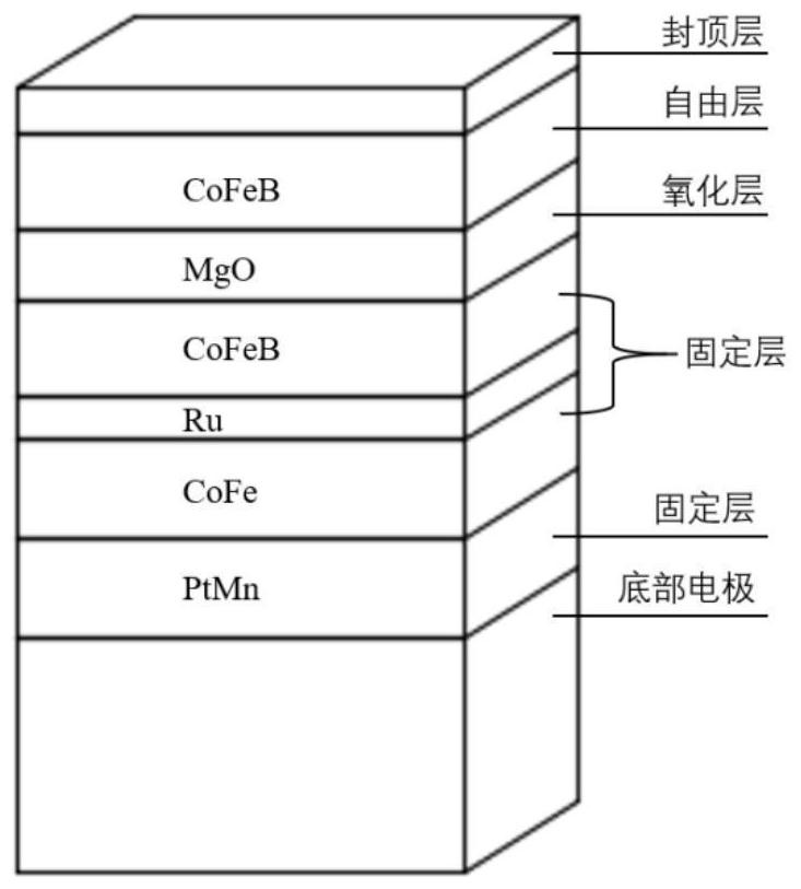

Image

  • Neural signal amplifier based on MTJ device
  • Neural signal amplifier based on MTJ device
  • Neural signal amplifier based on MTJ device

Examples


Embodiment 1

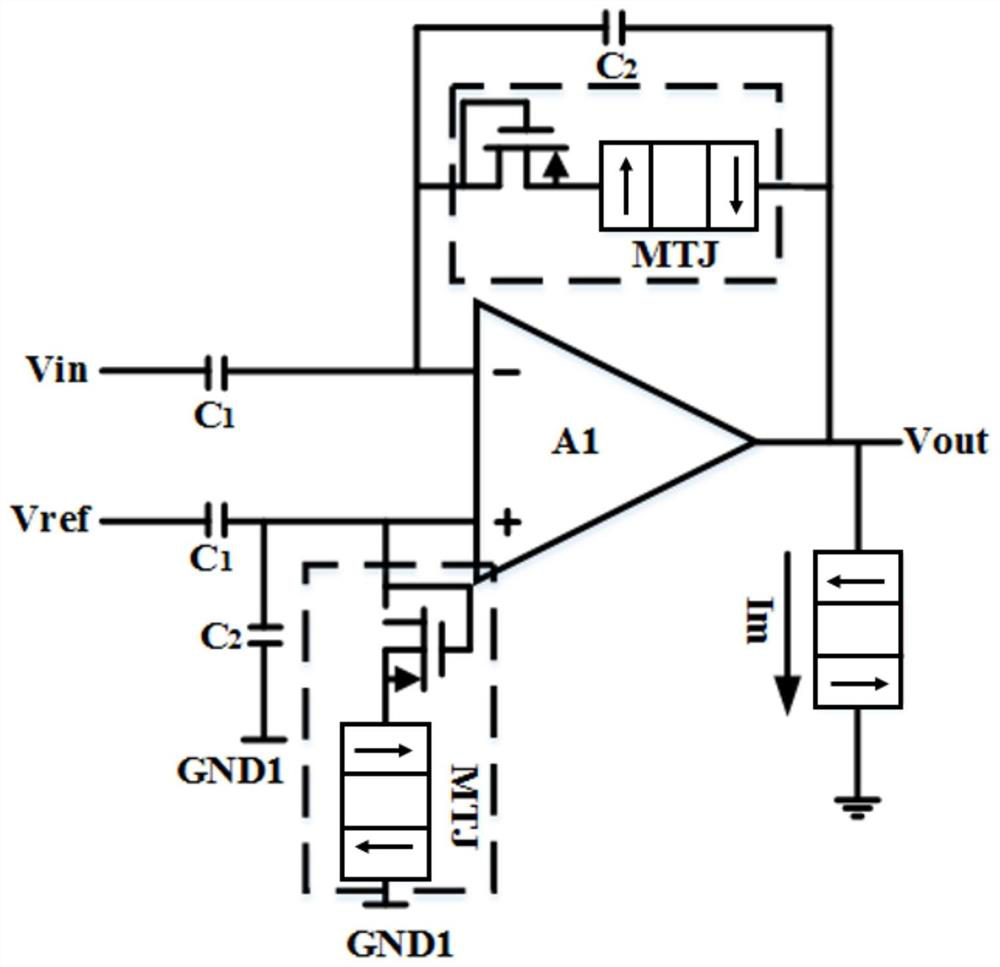
[0039] This embodiment provides a neural signal amplifier based on MTJ devices, such as image 3 As shown, including the internal operational amplifier and the amplifier feedback loop, the neural signal amplifier based on the MTJ device includes two amplifier feedback loops, both of which are composed of a pseudo-resistance RH and a capacitor C2, one of which is connected between the input and output of the negative terminal , and the other is connected between the positive input and ground.

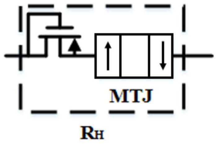
[0040] Such as figure 2 As shown, the pseudo-resistor RH is composed of MTJ and MOS transistors, wherein the gate and drain of the MOS transistors are short-circuited, and the base and source are short-circuited.

[0041] The output terminal of the internal operational amplifier is a push-pull common-gate common-source structure composed of four PMOS transistors, and MTJ is connected to the output terminal of the amplifier as a parallel resistor.

[0042] The neural signal is input to t...

Embodiment 2

[0059] This embodiment provides a brain-computer interface system, including the neural signal amplifier based on the MTJ device described in Embodiment 1, a microelectrode and a band-pass filter. The amplifier in the existing brain-computer interface system is to be replaced with the neural signal amplifier based on the MTJ device described in the first embodiment, so as to selectively amplify the signal in the frequency band below 300 Hz according to its amplitude, that is, only Effectively identify and amplify high-pulse nerve action signals.


PUM


Abstract

The invention discloses a neural signal amplifier based on an MTJ device, and belongs to the technical field of biological signal processing. An amplifier is provided with two amplifier feedback loops, a pseudo resistor RH is composed of an MTJ and an MOS tube, selective amplification is conducted on signals in the frequency band lower than 300 Hz according to the amplitude of the signals, and inother words, only high-pulse neural action signals are effectively recognized and amplified. The pseudo resistor RH is formed by connecting the MTJ and the MOS tube in series, so the problem that thepositive and negative directions of MOS current are not matched is solved, the noise is lower, the distortion of the amplifier is reduced, and the interference to a neural signal is also reduced. Dueto the fact that the pseudo resistor has extremely high resistance, the capacitor C2 can achieve a very low low-frequency cut-off point without a very large area, the chip area is reduced to a certainextent; in addition, the MTJ is directly manufactured in the fourth layer of metal and the fifth layer of metal through the MEMS technology, and the occupation of the chip area is also reduced.

Description

technical field [0001] The invention relates to a neural signal amplifier based on an MTJ device, belonging to the technical field of biological signal processing. Background technique [0002] Brain-computer interface, as the name suggests, is to establish a direct communication and control channel between the human brain and computers or other devices. other devices. Applying this technology to the medical field could improve the ability of severely disabled patients to communicate with the outside world or control their external environment. At the same time, the EEG interface is also helpful to observe the activity state of the nerve signal when the human body is stimulated by the outside world, and provide relevant information for further medical research. [0003] Existing brain-computer interface systems usually consist of microelectrodes, neural front-end amplifiers, and bandpass filters. Among them, the microelectrode is used to extract the nerve signal of the br...

Claims


Application Information

Patent Timeline
IPC IPC(8): H03F3/26H03F3/45H03F1/26H03F1/32
CPCH03F1/26H03F1/3205H03F1/3211H03F3/26H03F3/45
Inventor 姜岩峰李茹姜淋馨
Owner 南京明尼晶磁电子科技有限公司
Learn More