Self-adaptive low-pressure fuel oil distributor for multi-pipe pulse detonation combustor

A fuel distributor and pulse detonation technology, applied in the field of aero-engines, can solve the problems of large influence of pulsating pressure, complicated electronic control equipment, uneven fuel distribution, etc., to reduce pressure pulsation, good work synchronization, and high safety and reliability. Effect

Active Publication Date: 2020-09-29
NORTHWESTERN POLYTECHNICAL UNIV
View PDF15 Cites 0 Cited by
  • Summary
  • Abstract
  • Description
  • Claims
  • Application Information

AI Technical Summary

Problems solved by technology

[0007] In order to avoid the deficiencies of the prior art, the present invention proposes an adaptive low-pressure fuel distributor for multi-pipe pulse detonation combustion chambers. In the case of adaptive fuel supply, the fuel flow of each fuel branch is uniform, the structure is simple, the processing is simple, and the work is stable, which solves the multi-tube pulse detonation combustion chamber fuel self-adaption supply oil distributor, uneven fuel distribution, and pulsation in the detonation chamber The problems of large pressure influence, complex electronic control equipment and low reliability

Method used


Image

  • Self-adaptive low-pressure fuel oil distributor for multi-pipe pulse detonation combustor
  • Self-adaptive low-pressure fuel oil distributor for multi-pipe pulse detonation combustor
  • Self-adaptive low-pressure fuel oil distributor for multi-pipe pulse detonation combustor

Examples


Embodiment Construction

[0027] The embodiments described below by referring to the figures are exemplary and are intended to explain the present invention and should not be construed as limiting the present invention.

[0028] In describing the present invention, it should be understood that the terms "center", "longitudinal", "transverse", "length", "width", "thickness", "upper", "lower", "front", " Orientation indicated by rear, left, right, vertical, horizontal, top, bottom, inside, outside, clockwise, counterclockwise, etc. The positional relationship is based on the orientation or positional relationship shown in the drawings, which is only for the convenience of describing the present invention and simplifying the description, rather than indicating or implying that the referred device or element must have a specific orientation, be constructed and operated in a specific orientation, Therefore, it should not be construed as limiting the invention.

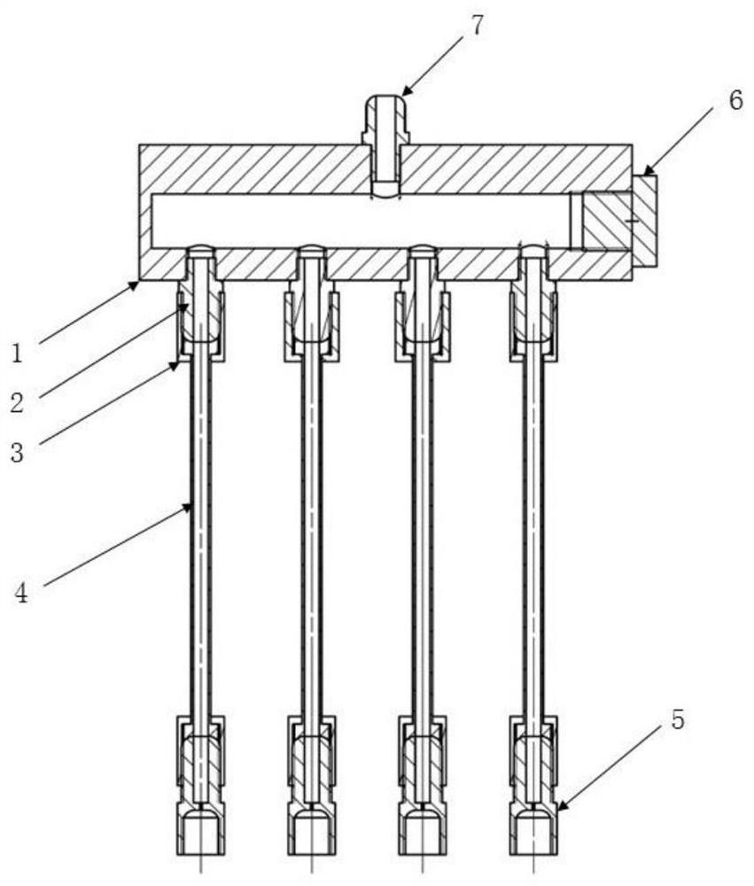
[0029] See figure 1 , an adaptive low-press...


PUM


Abstract

The invention relates to a self-adaptive low-pressure fuel oil distributor for a multi-pipe pulse detonation combustor and belongs to the field of aircraft engines. The self-adaptive low-pressure fueloil distributor comprises a low-pressure oil distribution cavity, fuel oil branches and pressure stabilizing sections; a fuel oil inlet is formed in the center of the top of the low-pressure oil distribution cavity, and a plurality of fuel oil outlets are formed in the bottom of the low-pressure oil distribution cavity at equal intervals; the plurality of pressure stabilizing sections communicatewith the fuel oil outlets of the low-pressure oil distribution cavity in a one-to-one correspondence manner through the fuel oil branches; each pressure stabilizing section is provided with a step through hole as a flow channel along a central shaft, the diameters of two ends of the step through hole are larger than the diameter of the middle part, and the section positioned in the middle part iscalled a thin-wall small hole; and the diameter of the thin-wall small hole is 0.010-0.025 times of the equivalent diameter of the detonation combustion chamber, and the axial length of the thin-wallsmall hole is 1-4 times of the diameter of the thin-wall small hole. Through the pressure stabilization of the low-pressure oil distribution cavity and the throttling of the thin-wall small holes ofthe pressure stabilizing sections, the fuel flow uniformity of each fuel oil branch of the distributor under the self-adaptive oil supply condition is effectively improved, the fuel backflow of the fuel oil branches caused by the gas pressure fluctuation in the detonation combustion chamber is reduced, the pressure pulsation in the oil distribution cavity is reduced, and the mutual interference among the fuel oil branches is reduced.

Description

technical field [0001] The invention belongs to the field of aero-engines, and in particular relates to an adaptive low-pressure fuel distributor for a multi-pipe pulse detonation combustion chamber. Background technique [0002] Detonation combustion has unique advantages such as fast propagation speed, self-pressurization, and low entropy increase in the combustion process. Therefore, the use of pulse detonation combustion in the engine can improve its cycle thermal efficiency, simplify the structure, increase the unit thrust of the engine and reduce fuel consumption. Rate. It has broad application prospects in the fields of unmanned aircraft, missiles and combined power devices, and is expected to become one of the most advanced power devices in the future. The miniaturization and weight reduction of the fuel accessory system of the multi-tube pulse detonation combustor, its core component, is a problem that must be solved to realize the engineering of this type of engin...

Claims


Application Information

Patent Timeline
Patent Type & Authority Applications(China)
IPC IPC(8): F02C7/228F02C7/22
CPCF02C7/222F02C7/228
Inventor 郑龙席谭汶昊王凌羿
Owner NORTHWESTERN POLYTECHNICAL UNIV
Why Eureka
Try Eureka