
Rodent small animal imaging device for ultrahigh-field magnetic resonance imaging system

A technology of magnetic resonance imaging and imaging equipment, applied in the direction of magnetic resonance measurement, measurement equipment, applications, etc., can solve problems such as inability to meet the requirements of complex research, achieve optimal reception efficiency, improve imaging quality, and high applicability

Pending Publication Date: 2020-09-29
杭州拉莫科技有限公司 +1
View PDF0 Cites 3 Cited by
  • Summary
  • Abstract
  • Description
  • Claims
  • Application Information

AI Technical Summary

Problems solved by technology

At present, the existing multi-core coils on the market are basically surface coils. In the actual process of animal experiments, if it is not drug anesthesia but gas anesthesia maintenance is required, it is necessary to design an additional gas anesthesia system that can be used in an ultra-high field environment.
Due to the inconvenience of maintaining gas anesthesia in an ultra-high field environment, most small animal magnetic resonance studies are currently carried out under drug anesthesia in small animals. Considering the toxicity of anesthetic drugs and the tolerance of small animals, most drugs It can only last for 2-4 hours, which cannot meet the requirements of some complex research in ultra-high field environment

Method used


Image

  • Rodent small animal imaging device for ultrahigh-field magnetic resonance imaging system
  • Rodent small animal imaging device for ultrahigh-field magnetic resonance imaging system
  • Rodent small animal imaging device for ultrahigh-field magnetic resonance imaging system

Examples


Embodiment Construction

[0043] The specific implementation manners of the present invention will be further described in detail below in conjunction with the accompanying drawings and embodiments. The following examples are used to illustrate the present invention, but are not intended to limit the scope of the present invention. In this embodiment, unless otherwise specified, the "left, right, front, and rear" mentioned in the text all refer to figure 1 For reference, in figure 1 Among them, "front" is parallel to the paper surface to the right, "rear" is parallel to the left surface of the paper surface, "left" is perpendicular to the paper surface inward, and "rear" is perpendicular to the paper surface outward.

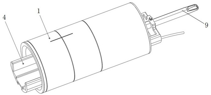
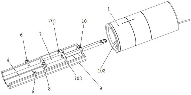
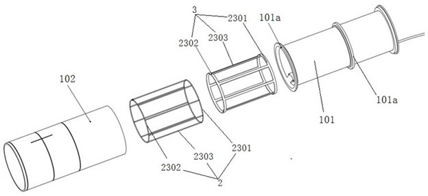
[0044] Figure 1 to Figure 5 It shows a rodent small animal imaging device for an ultra-high field magnetic resonance imaging system provided by the present invention, including a coil, a cylindrical coil support shell 1 and a support bed 4, and the coil includes a The hydrogen nuclea...


PUM


Abstract

The invention discloses a rodent small animal imaging device for an ultrahigh-field magnetic resonance imaging system. The rodent small animal imaging device comprises a cylindrical coil supporting shell, a hydrogen nucleus transmitting and receiving coil and a non-hydrogen nucleus transmitting and receiving coil, wherein the hydrogen nucleus transmitting and receiving coil and the non-hydrogen nucleus transmitting and receiving coil are arranged in a shell wall interlayer of the coil supporting shell; each of the hydrogen nucleus transmitting and receiving coil and the non-hydrogen nucleus transmitting and receiving coil comprises a front coil unit and a rear coil unit which are both of an annular structure and are arranged at intervals, and a plurality of straight wires which are connected with the front coil unit and the rear coil unit and are arranged at intervals in the circumferential direction. The hydrogen nucleus transmitting and receiving coil and the non-hydrogen nucleus transmitting and receiving coil are arranged in a sleeving mode, and each straight wire of the hydrogen nucleus transmitting and receiving coil is arranged between two corresponding adjacent straight wires on the non-hydrogen nucleus transmitting and receiving coil. The device provided by the invention can obtain a magnetic resonance image with higher quality and more comprehensive information.

Description

technical field [0001] The invention relates to the field of ultra-high-field magnetic resonance imaging systems, in particular to a small rodent imaging device used in the ultra-high-field magnetic resonance imaging system. [0002] technical background [0003] The phenomenon of nuclear magnetic resonance was first discovered by the scientific research team of Bloch and Purcell in 1946. Its basic principle is: under the action of an external magnetic field, some protons (including hydrogen protons in the human body) precessing around the main magnetic field (external magnetic field) ) under the action of a short radio frequency wave, the precession angle increases; when the radio frequency wave stops, those protons will gradually return to their original state, and at the same time release a radio frequency signal with the same frequency as the excitation wave. This physical phenomenon is called For nuclear magnetic resonance, the "nucleus" is removed in medical application...

Claims


Application Information

Patent Timeline
IPC IPC(8): G01R33/34A61B5/055
CPCA61B5/055A61B2503/40G01R33/34G01R33/34076
Inventor 张孝通陈俐利杨晓军肖桂山阮英恒
Owner 杭州拉莫科技有限公司
Learn More