
Microfluidic chip and its system for high-throughput magnetic separation of circulating tumor cells

A microfluidic chip and magnetic sorting technology, which is applied in fluid controllers, laboratory containers, and stress-stimulated microbial growth methods, can solve the problems of cumbersome transfer pipelines, CTC loss, and high experimental costs, and achieve The capture efficiency is the best, the cell shape is complete, and the effect of low capture rate is solved

Active Publication Date: 2020-12-04
BEIJING FRIENDSHIP HOSPITAL CAPITAL MEDICAL UNIV
View PDF5 Cites 0 Cited by
  • Summary
  • Abstract
  • Description
  • Claims
  • Application Information

AI Technical Summary

Problems solved by technology

However, the inventor also found that there are many problems in the sorting equipment and method during the experimental research.
First of all, the main function of the microfluidic chip is to remove background cells. The samples that pass through the microfluidic chip still need to rely on the existing commercial magnetic sorting equipment for CTC sorting, which makes the whole system too large in volume. The cost is high, and the transfer pipeline is cumbersome; secondly, the structure of the existing mature magnetic bead cell sorting equipment is mostly a magnetic column-like structure. During the sorting process, some cells will remain in the magnetic column, resulting in the loss of CTCs; finally, although the average clearance rates of the microfluidic chip for white blood cells, red blood cells, and platelets are: 99.3±1.6%, 99.6±0.8%, 99.9% ±1.2%, but the remaining background cells are still too large relative to the number of CTCs, and the extraction purity still needs to be improved

Method used


Image

  • Microfluidic chip and its system for high-throughput magnetic separation of circulating tumor cells
  • Microfluidic chip and its system for high-throughput magnetic separation of circulating tumor cells
  • Microfluidic chip and its system for high-throughput magnetic separation of circulating tumor cells

Examples


Embodiment 1

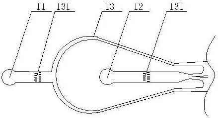
[0073] Such as figure 1 As shown, the present invention provides a microfluidic chip for high-throughput magnetic separation of circulating tumor cells. The microfluidic chip includes a sample inlet 1 , a microfluidic sorting area 2 and a sample outlet 3 . The microfluidic sorting area 2 is a closed chamber structure through which blood samples are filtered and sorted. Therefore, the sample inlet part 1 is used as a sample inlet channel for blood samples, and the sample outlet part 3 is used as a target cell sample outlet channel, both of which are respectively connected to the two ends of the microfluidic sorting area 2 . When the blood sample is injected, buffer solution needs to be injected to help the flow of the blood sample. Therefore, the sampling part 1 includes a blood sample inlet 11 and a buffer inlet 12 . The sample outlet 3 is used to separate different harvested cells, so the sample outlet 3 includes a magnetic bead cell collection port 31 and a non-magnetic be...


PUM

PropertyMeasurementUnit
widthaaaaaaaaaa
lengthaaaaaaaaaa
diameteraaaaaaaaaa

Abstract

The invention discloses a micro-fluidic chip for high-throughput magnetic separation of circulating tumor cells. The micro-fluidic chip comprises a sample feeding part, a micro-fluidic separation areaand a sample discharging part, wherein the micro-fluidic separation area is of a closed cavity type structure, and the sample feeding part and the sample discharging part are connected with the two ends of the micro-fluidic separation area respectively; the sample feeding part comprises a blood sample feeding port and a buffer solution inlet; the sample discharging part comprises a magnetic beadcell collecting opening and a non-magnetic bead cell collecting opening; the micro-fluidic separation area comprises three structural areas, namely a purification structural area, a cell focusing structural area and a magnetic bead separation structural area. The micro-fluidic chip is high in background cell clearance rate, high in tumor cell capture rate, high in tumor cell survival rate and capable of achieving high-throughput capture.

Description

technical field [0001] The invention relates to a microfluidic chip, in particular to a microfluidic chip for high-throughput magnetic separation of circulating tumor cells and a microfluidic chip system composed of the microfluidic chip. Background technique [0002] Tumor is a major disease that endangers human health in today's society. At present, the most effective way to treat tumors is surgical resection. However, even after surgical resection, patients still have a certain probability of tumor recurrence and metastasis. One of the reasons for the poor prognosis is cancer. Cells can easily enter and travel through the blood. Such free tumor cells may already be present in the blood of these patients prior to surgical resection. [0003] In 1896, Australian scholar Ashworth found cells similar to tumor cells in the peripheral blood of a patient who died of cancer, and thus proposed the concept of circulating tumor cells (CTC). CTC refers to some cancer cells that bre...

Claims


Application Information

Patent Timeline
Patent Type & Authority Patents(China)
IPC IPC(8): C12M1/42C12M1/00B01L3/00
CPCB01L3/502761B01L2200/0647B01L2300/0877B01L2400/043C12M23/16C12M47/04
Inventor 朱志军王学斌孙丽莹
Owner BEIJING FRIENDSHIP HOSPITAL CAPITAL MEDICAL UNIV
Learn More