Assembly method of rotor wing transmission mechanism, drone and aircraft

A technology of transmission mechanism and assembly method, which is applied in the direction of positioning device, metal processing machinery parts, clamping, etc., can solve the problems of inability to guarantee the consistency of batch products, difficulty in assembly, and difficulty in assembly, so as to ensure quality stability and Reliability, reduce the difficulty of assembly, and ensure the effect of reliability

Pending Publication Date: 2020-10-09
一飞智控(天津)科技有限公司
View PDF0 Cites 0 Cited by
  • Summary
  • Abstract
  • Description
  • Claims
  • Application Information

AI Technical Summary

Problems solved by technology

[0004] (1) During the assembly of parts, the method of manual reaming and drilling when assembling the limit pin installation hole is difficult to assemble, and the consistency of batch products cannot be guaranteed
[0005] (2) During the interference assembly of the limit pin, the local heating method of the transfer limit block is adopted, resulting in the existence of fine steps at the interface in the installation hole of the limit pin, which makes assembly difficult
The rotor system is the source of power for the UAV to fly, and the power system is the source of power for the UAV itself. The rotor transmission mechanism combines the two. If it fails, it will easily cause parking in the air and cause a crash.

Method used


Image

  • Assembly method of rotor wing transmission mechanism, drone and aircraft
  • Assembly method of rotor wing transmission mechanism, drone and aircraft

Examples


Embodiment Construction

[0039] In order to make the object, technical solution and advantages of the present invention more clear, the present invention will be further described in detail below in conjunction with the examples. It should be understood that the specific embodiments described here are only used to explain the present invention, not to limit the present invention.

[0040] Aiming at the problems existing in the prior art, the present invention provides an assembly method of a rotor transmission mechanism, a drone, and an aircraft. The present invention will be described in detail below with reference to the accompanying drawings.

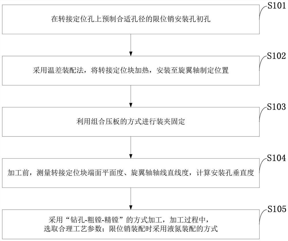
[0041] Such as figure 1 As shown, the assembly method of the rotor drive mechanism provided by the present invention comprises the following steps:

[0042] S101: Prefabricate the initial hole of the limit pin installation hole with a suitable diameter on the transfer positioning hole;

[0043] S102: Use the temperature difference assembly method to heat t...


PUM

PropertyMeasurementUnit
lengthaaaaaaaaaa

Abstract

The invention belongs to the technical field of mechanical assembly, and discloses an assembly method of a rotor wing transmission mechanism, a drone and an aircraft. The assembly method of the rotorwing transmission mechanism is characterized in that a limiting pin mounting hole initial hole is prefabricated in a transfer positioning hole; a hole is not preformed in a rotor wing shaft; a temperature difference assembly method is adopted, and a switching positioning block is heated and installed at the set position of the rotor shaft; the limiting pin mounting hole is machined by using a numerically-controlled machine tool; machining is conducted in the modes of drilling, rough boring and fine boring; and a liquid nitrogen assembling mode is adopted when a limiting pin is assembled. According to the assembly method of the rotor wing transmission mechanism, the drone and the aircraft, the precise numerical control machine tool is adopted for drilling, so that the assembly precision andthe quality stability are improved, and the reliability of a drone product is guaranteed; the liquid nitrogen assembling method is adopted, so that the assembling difficulty caused by tiny hole diameter difference due to different temperatures under the temperature difference assembling of the switching positioning block and the rotor wing shaft is avoided, and the assembling difficulty of the rotor wing transmission mechanism is reduced; and the rotor wing shaft, the switching positioning block and the limiting pin can be assembled in a high-precision and high-quality manner, and the qualitystability and reliability of the product are guaranteed.

Description

technical field [0001] The invention belongs to the technical field of mechanical assembly, and in particular relates to an assembly method of a rotor transmission mechanism, a drone, and an aircraft. Background technique [0002] At present, in order to ensure the reliability of the structure, the rotor transmission mechanism of large UAVs does not adopt the traditional gear or belt structure, but uses the "interference + limit" method to make the transfer positioning block and the rotor shaft interfere. At the same time, a radial limit pin is added to prevent the interference structure from failing under high torque, and the limit pin is also an interference fit, wherein the transfer positioning block is made of high-strength aluminum alloy material, and the rotor shaft and limit pin are structural steel. When assembling the parts, the installation holes of the limit pins are generally prefabricated in the initial hole, and then manually reamed and drilled during assembly...

Claims


Application Information

Patent Timeline
Patent Type & Authority Applications(China)
IPC IPC(8): B23Q3/06B23Q17/00B23P11/02
CPCB23P11/025B23Q3/062B23Q17/00
Inventor 张云张朋朋王喜胜
Owner 一飞智控(天津)科技有限公司
Why Eureka
Try Eureka