[0021] In order to make the objectives, technical solutions and advantages of the present invention clearer, the following describes the technical solutions in the embodiments of the present invention clearly and completely with reference to the accompanying drawings and specific embodiments. Obviously, the described embodiments are only the present invention. Part of the embodiments, but not all of the embodiments. It should be understood that the specific embodiments described herein are only used to explain the present invention, but not to limit the present invention.
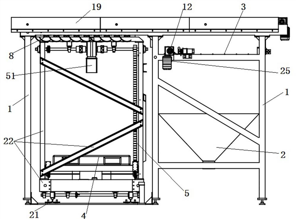
[0022] Such as figure 1 As shown, the present invention provides a packaging bag opening device, which includes a frame 1 and a bag grabbing and feeding mechanism and a bag breaking mechanism arranged on the frame 1. The bag grabbing and feeding mechanism is provided Above the bag breaking mechanism, the bag grabbing and feeding mechanism is connected to the pushing mechanism, and the pushing mechanism is arranged on the top of the frame 1. The bag grabbing and feeding mechanism can hook the packaging bag on the platform 4, The pushing mechanism is used to push the packaging bag through the bag breaking mechanism to be broken, and the materials in the packaging bag fall into the storage bin 2 on the other side of the bag breaking mechanism. Place the packaging bag with plastic granular material on the platform below the bag grabbing and feeding mechanism. The bag grabbing and feeding mechanism moves to the top of the platform with the pushing mechanism, and the bag grabbing mechanism is used to hook the packaging bag and drag it with the pushing mechanism. Demolition is carried out at the bag breaking mechanism, and the materials in the broken packaging bag fall into the storage bin on the other side during the pushing process of the pushing mechanism.
[0023] In a specific embodiment of the present invention, such as Figure 1-4 As shown, the bag grabbing and feeding mechanism includes a frame 7, a telescopic part 6, and several rows of grappling hooks 8 arranged in the frame 7. There are several grappling hooks 8 in each row and they are all fixed on a rotating shaft 9. The rotating shaft The two ends of 9 are rotationally matched with the side frame of the frame 7 through the bearings 23, and several rotating shafts 9 are arranged side by side in the frame 7; the middle part of the rotating shaft 9 is connected to the telescopic part 6 by a link mechanism, and the telescopic part 6 is arranged obliquely On one side beam 70 of the frame 7, it is used to drive the rotating shaft 9 and the grab hook 8 to rotate to hook or detach the packaging bag below; the frame 7 is connected with a pushing mechanism. The telescopic component drives the rotating shaft to rotate through the linkage mechanism, and then drives the multiple grappling hooks on the rotating shaft to rotate at the same time, which can hook or detach the packaging bag.
[0024] In a specific embodiment of the present invention, such as figure 2 , 4 As shown, the telescopic component 6 is a grapple cylinder, the cylinder of the grapple cylinder is hinged with the end beam 70 of the frame 7, and the end of the piston rod of the grapple cylinder is connected with the connecting rod mechanism; The rod mechanism includes a connecting rod 10 and a connecting rod 11 connected to a rotating shaft 9. One end of the connecting rod 11 is radially fixed on the surface of the rotating shaft 9, and the other end of the connecting rod 11 is rotatably connected to the connecting rod 10. The middle of the rod 10 is rotatably connected with the end of the piston rod of the grapple cylinder; the connecting rod 10 and the rotating shaft 9 are arranged in a crisscross pattern, and the connecting rod 10 and the piston rod of the grapple cylinder are in the same plane. In this solution, the connecting rod can be moved up and down through the telescopic action of the grapple cylinder, and then several rows of rotating shafts can be driven to rotate simultaneously through the connecting rod.
[0025] Further optimize the above technical solutions, such as figure 2 , 4 As shown, there are two connecting rods 10 and two grapple cylinders. Each rotating shaft 9 is provided with two connecting rods 11, and the connecting rods 11 on both sides of the several rotating shafts 9 rotate with the connecting rod 10. For connection, the connecting rod 10 and the grappling hook cylinder are both arranged above the rotating shaft 9, and the lower surface of the connecting rod 10 is rotatably connected with a plurality of connecting rods 11 at intervals. Adopting this structure to improve the driving force can ensure the movement consistency and stability of all rotating shafts and grappling hooks.
[0026] In a specific embodiment of the present invention, such as image 3 As shown, the grappling hook 8 includes a connecting portion 81 and a hook pocket portion 82. One end of the connecting portion 81 is radially fixed to the surface of the rotating shaft 9 and the other end of the connecting portion 81 is connected to the hook pocket portion 82. The hook pocket 82 is an arc-shaped hook with the rotating shaft 9 as the central axis. Among them, the arc-shaped hook can be designed as a superior arc to ensure that the packaging bag is hooked firmly; the connecting part 81 and the connecting rod 11 are arranged at an acute angle, and the hook bag part can be driven to hook or leave the lower packaging bag without two deflection too large.
[0027] In a specific embodiment of the present invention, such as figure 1 , 4 As shown, the bag breaking mechanism includes a rotating shaft 12 and a plurality of blades 13 on the rotating shaft 12. The rotating shaft 12 is driven by a bag breaking motor 25, and the rotating shaft 12 is arranged between the frame 7 and the storage bin 2. At the junction and above the storage bin 2, the rotating shaft 12 is arranged below the frame 7. The motor drives the rotating shaft and the multiple blades on it to rotate at a high speed. When the packaging bag passes over it and touches the blade, the lower surface of the packaging bag can be smoothly damaged. The plastic particles in the packaging bag will be the same as the damaged packaging bag during the movement. Can fall into the storage bin below.
[0028] In a specific embodiment of the present invention, such as Figure 4 As shown, the pushing mechanism includes a conveyor belt 14 and a driving part. The side wall of the frame 1 is provided with a guide rail 15 that cooperates with a frame 7, and the frame 7 is fixed to the lower half of the conveyor belt 14; the driving part includes The driving motor 16, the driving wheel 17 and the driven wheel (not shown in the figure), the driving motor 16, the driving wheel 17 and the driven wheel are all arranged on the frame 1, the driving wheel 17 and the driven wheel are respectively arranged on the conveyor belt Both ends of 14. Among them, there are two conveyor belts 14 which are connected to both sides of the frame 7 respectively. The driving wheels 17 and driven wheels of the two conveyor belts 14 are respectively arranged at both ends of the driving shaft 18 and the driven shaft (not shown in the figure). Among them, the drive motor is a servo motor or a stepping motor, and the frame is driven to reciprocate between the storage bin and the feeding station through the forward and reverse rotation of the drive motor. In order to facilitate unloading, the height of the bag breaking mechanism and the empty bag support frame of the bag breaking station is lower than the height of the bag grabbing and feeding mechanism. The conveyor belt drives the rows of grappling hooks inside the frame to hook the packaging bag at the loading station, and the packaging bag contacts the rotating blade of the bag breaking station during the translation process to achieve the end of the damaged packaging bag, and then the plastic particles in the packaging bag Fall into the storage bin below while continuing to move.
[0029] In a specific embodiment of the present invention, such as figure 1 , 4 As shown, the top of the storage bin 2 is provided with an empty bag support frame 3, the empty bag support frame 3 is a grid structure, used to support the empty bags after discharge; the storage bin 2 and The empty bag support frame 3 is respectively arranged at the upper and lower part of the frame 1, the empty bag support frame 3 is arranged under the bag grabbing and feeding mechanism and the pushing mechanism; the top edge of the frame 1 is provided with a guard plate 19, One side of the protective plate 19 is provided with a bag outlet 20 corresponding to the empty bag support frame 3. With this structure, the empty bags that have been broken and disassembled can be left on the empty bag support frame, which facilitates the recovery of the remaining empty bags.
[0030] The present invention also provides a bag opening machine, which includes the above-mentioned bag opening device, and any bag opening machine containing the above-mentioned structure of the bag opening device falls within the protection scope of the present invention.
[0031] in figure 1 , 4 In the specific embodiment shown, the lower part of the bag grabbing and feeding mechanism is loaded by an elevator, and the platform 4 for placing the packaging bags is driven up and down by the elevator 5 to lift the packaging bag to a height to cooperate with the grabbing and feeding mechanism. Among them, the elevator can be a chain elevator, and a forklift can be used to put the whole bag of plastic particles on the platform of the loading station, and the elevator can be raised to the height that matches the bag-grabbing and feeding mechanism. To further optimize this solution, the bottom of the frame 1 is provided with a track 21, the feeding mechanism is arranged in a fixed frame 22, and the fixed frame 22 is driven by a translation mechanism to move between different storage bins on the track 21. Multiple packaging bags can be staggered to a high position, and the grappling hook is driven to hook the packaging bag to realize the staggered opening and unloading of multiple packaging bags, which greatly improves work efficiency. Among them, the fixed frame is a frame structure, the fixed frame is connected with the translation mechanism, and it can be translated to any loading station along the track, which is flexible and convenient; the lifting platform inside the fixed frame moves up and down under the drive of the elevator to realize the lifting of the packaging bag. material. The fixed frame connected with the translation mechanism is equivalent to a translation trolley running on the track, which is convenient and quick to operate.
[0032] In summary, the present invention has the advantages of simple and compact structure, convenient and quick operation, and high degree of mechanization. The bag-grabbing and feeding mechanism is pushed to the top of the platform on which the packaging bag is placed through the conveyor belt, and the grab hook is driven to hook the packaging bag. With the movement of the conveyor belt, the packaging bag is dragged to the top of the storage bin. The lower surface of the packaging bag is in contact with the high-speed rotating blade during the movement to realize the destruction of the packaging bag. After the packaging bag is damaged, the plastic particles fall to the storage material below. In the warehouse, the remaining empty bags are left on the empty bag support frame for easy recycling. The use of the present invention to break the packaging bag can reduce the labor intensity of operators, improve work efficiency, and is particularly suitable for mass production.
[0033] Specific examples are used in this article to describe the principle and implementation of the present invention. The description of the above examples is only used to help understand the method and core idea of the present invention. It should be pointed out that for those of ordinary skill in the art, without departing from the principle of the present invention, several improvements and modifications can be made to the present invention, and these improvements and modifications also fall within the protection scope of the claims of the present invention.