Blade gas-heat deicing system and mounting method thereof

A blade and gas heating technology, applied in the installation/supporting configuration of wind turbines, monitoring of wind turbines, wind power generation, etc., can solve problems such as dissipation and low heating efficiency, achieve firm fixation, improve heating efficiency, and reduce costs Effect

Active Publication Date: 2020-10-09
HUNAN TUOTIAN ENERGY SAVING CONTROL TECH
View PDF14 Cites 2 Cited by
  • Summary
  • Abstract
  • Description
  • Claims
  • Application Information

AI Technical Summary

Problems solved by technology

[0008] The technical problem to be solved by the present invention is that the hot air of the air-heat deicing system is easy to escape from the gap, resulting in low heating efficiency for the blades, and there are many hand-laid parts. In order to solve this problem, the present invention provides a blade air-heating The deicing system and its installation method have no gaps, which can avoid the escape of hot air and improve the heating efficiency of the blades. During installation, the ventilation pipes and heaters are installed with hoops, which greatly reduces the manual work of soaking epoxy resin with glass fiber cloth. Paste the installation content, reduce pollution and harm to the human body, save construction time, reduce costs, and reduce the loss of power generation when the owner shuts down. Ventilation pipes and heaters can be disassembled and replaced, which is convenient for subsequent maintenance and upgrades

Method used


Image

  • Blade gas-heat deicing system and mounting method thereof
  • Blade gas-heat deicing system and mounting method thereof
  • Blade gas-heat deicing system and mounting method thereof

Examples


Embodiment Construction

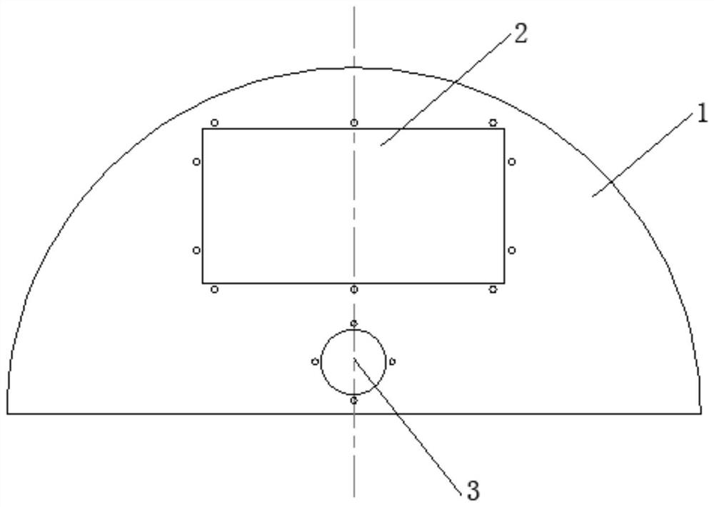
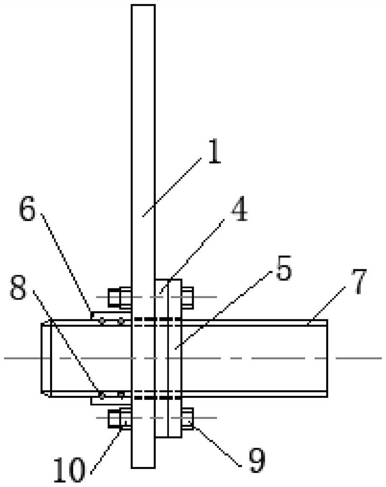
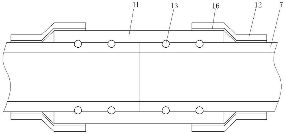
[0052] as attached figure 1 and figure 2 As shown, an aerothermal deicing system for a blade includes a heater, a ventilation duct 7, several hoops, a blower, a baffle 1 and a wiring bracket, and the baffle 1 is bonded between the web and the leading edge of the blade , the baffle plate 1 divides the leading edge cavity between the web and the leading edge of the blade into the first leading edge cavity and the second leading edge cavity, the baffle plate 1 is provided with a mounting hole 3, and several hoops are arranged along the length of the blade The direction is evenly bonded on the web of the blade, the heater is installed in the hoop, the air inlet of the heater is connected with the air outlet of the blower, the air outlet of the heater is connected with the air inlet at one end of the ventilation duct 7, and the ventilation duct 7 Installed in the hoop, the lower part of the blower is provided with a blower bracket, and the blower bracket is bonded on the blade ro...


PUM


Abstract

The invention relates to the field of blade gas-heat deicing, in particular to a blade gas-heat deicing system and a mounting method thereof. The blade gas-heat deicing system comprises a heater, a ventilation pipeline, a plurality of hoops, an air blower, a baffle plate and a wiring support, the baffle plate divides a leading edge cavity between a web and the leading edge of a blade into a firstleading edge cavity and a second leading edge cavity, an air inlet of the heater is connected with an air outlet of the air blower, an air outlet of the heater communicates with an air inlet in one end of the ventilation pipeline, and the other end of the ventilation pipeline penetrates through a mounting hole and is located in the first leading edge cavity of the blade. According to the blade gas-heat deicing system and the mounting method thereof, the baffle plate is bonded to the blade, so that it is guaranteed that no gap exists between the baffle plate and the blade and the baffle plate and the blade are firmly fixed, and hot air is prevented from escaping; and the ventilation pipeline and the heater are installed by adopting the hoops, and bonding is carried out on a signal line anda power line by adopting an adhesive tape, so that the content of mounting epoxy resin hand lay-up soaked in glass fiber cloth is greatly reduced, pollution and harm to the human body are reduced, theconstruction time is saved, the cost is reduced, and the shutdown power generation loss of an owner is reduced.

Description

technical field [0001] The invention relates to the field of blade aerothermal deicing, in particular to a blade aerothermal deicing system and an installation method thereof. Background technique [0002] During the operation of wind turbines, the blades of the wind turbines will be tested by various harsh environments, and the ice formation on the surface of the blades in the cold environment is the main factor that hinders the operation of wind turbines in cold weather. Icing of the wind turbine blades will cause the power generation of the wind turbine to decrease or even shut down. The unbalanced mass of the blades after icing will increase the fatigue damage at the bottom of the tower. [0003] At present, some patents at home and abroad have protected the blade deicing technology. Chinese Patent Publication No. CN102748243A discloses a wind turbine blade with anti-icing and deicing capabilities. A heating blower is installed near the blade root, and A heat insulation...

Claims


Application Information

Patent Timeline
Patent Type & Authority Applications(China)
IPC IPC(8): F03D80/40F03D80/60F03D17/00F03D80/55F03D13/20
CPCF03D80/40F03D80/60F03D17/00F03D80/55F03D13/20Y02E10/72Y02E10/728
Inventor 刘志龙周国文
Owner HUNAN TUOTIAN ENERGY SAVING CONTROL TECH
Why Eureka
Try Eureka