
Intelligent detection method for conveyor belt damage conditions

A technology of conveyors and belts, applied in image data processing, instruments, calculations, etc., can solve the problems of low detection accuracy, increase the complexity of system structure, and high image dependence, and achieve high accuracy of detection results and implementation means Novel and accurate results

Active Publication Date: 2020-10-09
XIDIAN UNIV
View PDF6 Cites 4 Cited by
  • Summary
  • Abstract
  • Description
  • Claims
  • Application Information

AI Technical Summary

Problems solved by technology

[0003] The first category is to use manual inspection in long-distance and large transportation systems, which is labor-intensive and has the problem of missed inspections;
[0004] The second category is the human-computer interaction mode in which the control part of the detection system is mostly controlled by humans, which can easily overload the entire system and cause potential safety hazards;
[0005] The third category is to use mechanical contact detection devices, such as magnetic sensors, pressure test devices, etc. One of the most fatal shortcomings of such devices is that their detection occurs after the accident, and it is impossible to predict the belt in advance. The operation status lacks real-time performance, and the maintenance tasks of the detection equipment are relatively heavy, and it is difficult to replace the relevant parameter components, which brings difficulties to the work of the maintenance personnel.
However, this method still has two deficiencies: First, the BP network is too dependent on the collected images. If the light source is not uniformly illuminated or the entire system shakes during the image collection process, it will be unfavorable to the evaluation of the network. Second, when the belt running speed is too fast or too slow, the detection accuracy is not very high
Although the device is easy to maintain and avoids the problems of high false detection rate of traditional sensor detection, it will undoubtedly increase the complexity of the system structure if the camera scan is to completely match the running speed of the belt; at the same time, because the device is not particularly prominent in the detection algorithm The optimization affects the improvement of detection speed and accuracy

Method used


Image

  • Intelligent detection method for conveyor belt damage conditions
  • Intelligent detection method for conveyor belt damage conditions
  • Intelligent detection method for conveyor belt damage conditions

Examples


Embodiment Construction

[0035] The implementation of the present invention is described in detail below in conjunction with accompanying drawing:

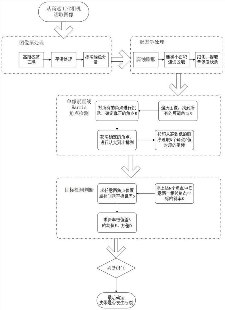
[0036] refer to figure 1 In this example, the method for detecting the damage status of the conveyor belt is carried out, and the implementation steps are as follows:

[0037] Step 1, collect the image of the belt to be tested.

[0038] 1.1) Install the test device:

[0039] Load the linear laser generator and adjust it to the position to ensure that the emitted green laser beam can be irradiated on the side of the belt, and at the same time connect its control circuit to the test box;

[0040] Load a high-speed industrial camera and adjust its position to ensure that the detection target image with the best viewing angle can be captured, and at the same time connect it to the test box;

[0041] The test box sends control instructions to make the linear laser generator generate a linear green laser beam whose intensity meets the best resolution of the ...


PUM


Abstract

The invention discloses an intelligent detection method for the damage condition of a belt of a conveyor, and mainly solves the problems that in the prior art, the tearing damage condition in the operation process of the belt conveyor cannot be detected in real time, and the false detection rate is high. The implementation scheme is as follows: 1) collecting an image of a to-be-detected belt; 2) sequentially carrying out cutting, denoising, normalization, expansion corrosion, convolution operation and smoothing processing on the image of the to-be-detected belt to obtain a new matrix M1; 3) calculating an angular point response function corresponding to each pixel by the new matrix M1, performing non-maximum suppression arrangement on the angular point response function, and solving a slope extreme value difference S; and 4) comparing the slope extreme value difference S with a given discrimination threshold k, if S is greater than k, the belt being torn, and if S is less than k, the belt being not torn. The method is high in detection speed and low in false detection rate, can detect the damage condition of the belt in real time, and can be used for detecting the damage conditionof the belt in the mechanical transmission process in mining industry, metallurgy and coal plants.

Description

technical field [0001] The invention belongs to the technical field of detection instruments, and in particular relates to an intelligent detection device, which can be used for detection of belt damage during mechanical transmission. Background technique [0002] In many metallurgical plants, high-grade refineries and coal mine industrial plants, belt transmission is undoubtedly a relatively common and widely used mode of cargo transportation, and the long transportation distance and the weight of the cargo make the belt face a greater challenge. Risk of breakage and tearing. Once the transport belt is torn, it will cause a huge amount of material damage and cause serious economic losses, so it is necessary to do safety inspection and related maintenance on the damaged belt. However, the traditional damage detection method is too simple and mechanized, and there are obvious deficiencies and flaws in many aspects such as cost, detection time, detection accuracy, real-time p...

Claims


Application Information

Patent Timeline
IPC IPC(8): G06T7/00G06T5/00G06T7/90G06T5/30G06T7/11G06T7/136G06T7/194G06T7/62
CPCG06T7/0008G06T7/90G06T5/30G06T7/11G06T7/136G06T7/194G06T7/62G06T2207/10004G06T2207/20132G06T2207/30164G06T5/70Y02P90/30
Inventor 王琳陈大秀郭亮成孝孝杨恒张坤席国博张兴国
Owner XIDIAN UNIV
Learn More