Adjustable combined type electronic heat dissipation device

A radiator and combined technology, which is applied in the direction of electrical components, electrical equipment structural parts, cooling/ventilation/heating transformation, etc., can solve the problems of narrow application range, inconvenient disassembly and replacement, and reduced heat dissipation efficiency, so as to achieve large heat dissipation and The contact area meets the needs of heat dissipation and improves the effect of heat dissipation energy efficiency

Active Publication Date: 2020-10-09
镇江元普电子科技有限公司
View PDF5 Cites 0 Cited by
  • Summary
  • Abstract
  • Description
  • Claims
  • Application Information

AI Technical Summary

Problems solved by technology

The fins in the prior art are made of steel, steel-aluminum composite, copper, copper-aluminum composite, stainless steel and other materials. According to the gear and installation position of the electronic device, the space for the device is reserved, and then contact heat transfer. The scope of application is narrow and it is inconvenient to replace. , The cost is high. At the same time, as the length of the heat dissipation profile from the heating device increases, the attenuation of air circulation makes it difficult to dissipate heat quickly. Therefore, in the prior art, air cooling or water cooling is also used to cooperate with the profile heat sink, and the contact time between the air and the profile heat sink Shorter, resulting in lower heat dissipation efficiency, difficult to meet the needs of use

Method used


Image

  • Adjustable combined type electronic heat dissipation device
  • Adjustable combined type electronic heat dissipation device
  • Adjustable combined type electronic heat dissipation device

Examples


Embodiment Construction

[0026] The specific embodiments of the present invention will be further described below in conjunction with the accompanying drawings.

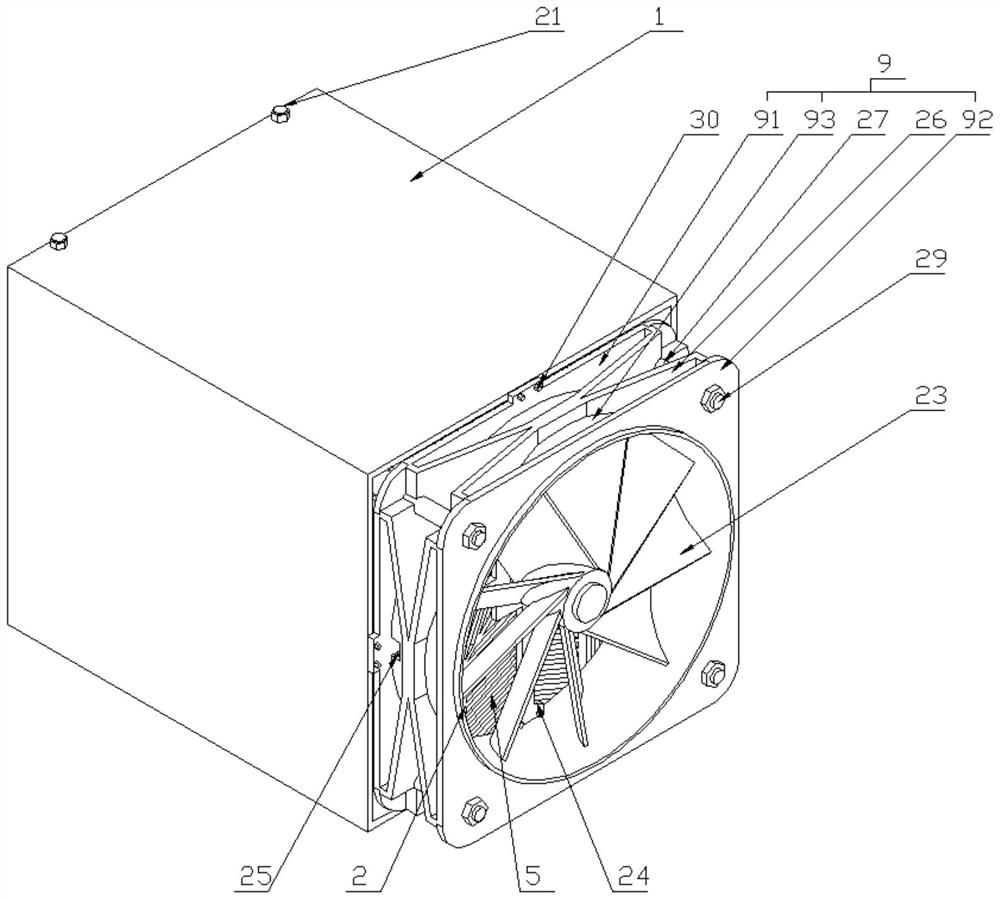
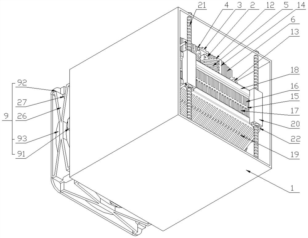
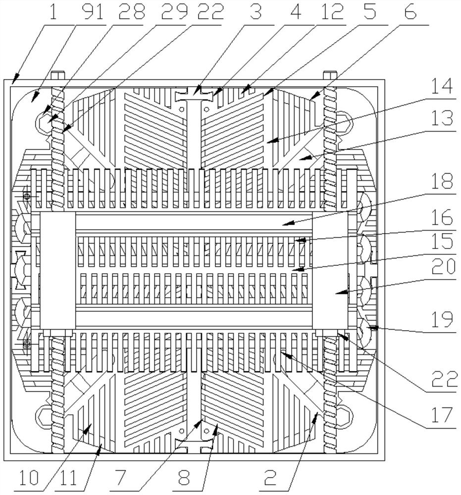
[0027] An adjustable combined electronic radiator, including a box body 1, wherein, the box body 1 is provided with four angular heat sinks 2 arranged symmetrically at intervals and mated with the inner wall of the box body 1, and the box body 1. A cutting strip 3 is provided on the inner wall, and a socket 4 matching the shape of the cutting strip 3 is provided on the inner wall of the corner radiator 2, and the two ends of the socket 4 are oppositely flared;

[0028] The corner heat sink 2 is provided with a plurality of first notches 5 and second notches 6 arranged symmetrically with respect to the diagonal of the box body 1 and distributed at intervals. The first notch 5 is vertically provided with corners The cooling body 2 is connected with a number of first folded plates 7 and second folded plates 8 arranged in dislocation intervals, ...


PUM


Abstract

The invention relates to an adjustable combined type electronic heat dissipation device, which comprises a box body, wherein four corner heat dissipation bodies which are matched with the inner wall of the box body in an inserted mode and are symmetrically arranged at intervals are arranged in the box body; a plurality of first notches and a plurality of second notches are formed in the corner heat dissipation bodies; a plurality of first folded plates and second folded plates which are connected with the corner heat dissipation bodies and are arranged in a staggered manner are vertically arranged on the first notches; a plurality of third folded plates and fourth folded plates are arranged on the second notches; a plurality of third notches and fourth notches are formed in the inner wallof end heat dissipation bodies; adjusting screw rods are arranged in supporting blocks of the bosses of the end heat dissipation bodies; an adjusting nut is arranged outside each adjusting screw rod;the head ends of the four corner heat dissipation bodies are each connected with a fan cover internally provided with a fan; and an S-shaped cold water pipes are arranged in the end heat dissipation bodies. According to the adjustable combined type electronic heat dissipation device, the four detachable corner heat dissipation bodies which are matched in an inserted mode are combined with the adjustable end heat dissipation bodies, the installation is convenient, the application range of the electronic heat dissipation device is widened, the larger heat dissipation and contact area is achieved, heat dissipation energy efficiency is improved through air cooling and water cooling combination and baffling, and the heat dissipation use requirements of electronic components are met.

Description

technical field [0001] The invention relates to an adjustable combined electronic radiator, which belongs to the technical field of electronic radiators. Background technique [0002] Electronic heat sink is a heat dissipation structure used for heat dissipation of high-power electronic components. It is widely used in power devices, module components, resistors, frequency converters, electric welding machines, power supplies, graphics cards and other fields. It mainly dissipates heat through air convection. The combined radiator achieves the purpose of cooling by increasing the heat dissipation area through the profile fins. The fins in the prior art are made of steel, steel-aluminum composite, copper, copper-aluminum composite, stainless steel, etc., according to the gear and installation position of the electronic device, reserve a space for device coordination, and then contact heat transfer. The scope of application is narrow and it is inconvenient to replace. , The co...

Claims


Application Information

Patent Timeline
Patent Type & Authority Applications(China)
IPC IPC(8): H05K7/20
CPCH05K7/20145H05K7/20272
Inventor 冷元媛
Owner 镇江元普电子科技有限公司
Why Eureka
Try Eureka