
Automatic stroke adjusting mechanism and method for gear machining tool

A processing machine tool and automatic adjustment technology, which is applied in the direction of metal processing machinery parts, metal processing equipment, manufacturing tools, etc., can solve the problems of complex mechanism, increased mechanical and electrical control costs, large volume, etc., and achieve reliable connection and easy quality assurance , sports accurate effect

Pending Publication Date: 2020-10-13
宜昌长机科技有限责任公司
View PDF0 Cites 0 Cited by
  • Summary
  • Abstract
  • Description
  • Claims
  • Application Information

AI Technical Summary

Problems solved by technology

[0002] The stroke adjustment of the motion mechanism in traditional gear processing machine tools is adjusted manually, and some special two-axis numerical control mechanisms are designed for automatic adjustment. When the mechanism reaches the required position, the position of its motion mechanism must be manually measured, and a special two-axis numerical control mechanism is designed for automatic clamping. Mechanical and Electrical Control Costs

Method used


Image

  • Automatic stroke adjusting mechanism and method for gear machining tool

Examples


Embodiment 1

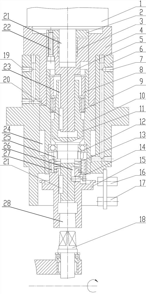
[0029] See figure 1 , An automatic stroke adjustment mechanism for a gear processing machine tool, which includes a support 6 in which a piston cavity 24 is machined, and an oil cylinder piston 10 is installed inside the piston cavity 24. A positioning disk 4 is fixedly installed on the top of the support 6 to block the top of the piston cavity 24; a servo motor 1 is fixedly installed on the top of the positioning disk 4, and the output end of the servo motor 1 is the same as the output shaft. 5 is connected; the bottom end of the output shaft one 5 is matched with the output shaft two 11 through a feather key structure, and drives the output shaft two 11 to rotate; the output shaft two 11 is positioned and installed inside the cylinder piston 10 through a bearing assembly, The piston 10 of the oil cylinder drives it to slide along the axial direction; the piston cavity 24 is connected with the oil supply structure for driving its movement; the lower part of the output shaft 11...

Embodiment 2

[0040] A method for adjusting the stroke of the automatic stroke adjustment mechanism of a gear processing machine tool:

[0041] Step 1: Supply oil through the oil inlet and outlet holes No. 19, return oil through the oil inlet and outlet holes No. 7, and the cylinder piston 10 moves downward, driving the output shaft No. 11 and the connecting square head 15 to move downwards, connecting the square head 15 with the drive screw After the outer square head of 18 is fully fitted, the cylinder piston 10 continues to move downwards, compressing the compression spring 13 until the lower end of the cylinder piston 10 fits with the end surface of the support 6, and the sending head 17 sends a signal;

[0042] Step 2: Servo motor 1 rotates to drive output shaft one 5, output shaft two 11, connecting square head 15, and drive screw 18 to rotate. After the drive screw 18 drives the motion mechanism to the specified position, the servo motor 1 stops rotating;

[0043] Step 3: Oil inlet 7 enters...


PUM


Abstract

The invention provides an automatic stroke adjusting mechanism and method for a gear machining machine tool. A piston cavity is machined in a support, an oil cylinder piston is installed in the pistoncavity, and a positioning disc is fixedly installed at the top of the support; the output end of a servo motor is connected with a first output shaft; the bottom end of the first first output shaft is matched with a second output shaft through a sliding key structure; the second output shaft is positioned and installed in the oil cylinder piston through a bearing assembly; the piston cavity is connected with an oil supply structure for driving the piston cavity to move; and a connecting square head is installed at the lower part of the second output shaft through a transmission flat key, andthe connecting square head is matched with a transmission screw rod which is located under the connecting square head. The automatic stroke adjusting mechanism and method are suitable for automatically adjusting the stroke of a movement mechanism in the gear machining tool, the stroke is automatically adjusted when the adjusting mechanism is connected with the movement mechanism, and the movementmechanism can automatically rotate only after the adjusting mechanism is disengaged from the movement mechanism.

Description

Technical field [0001] The invention belongs to the technical field of gear processing, and particularly relates to an automatic stroke adjustment mechanism and method for gear processing machine tools. Background technique [0002] The adjustment of the movement mechanism stroke in the traditional gear processing machine tool is adjusted manually, and some are designed with a dedicated two-axis CNC mechanism for automatic adjustment. Its biggest disadvantage is that it is adjusted manually, requiring manual rotation of the drive screw to make the movement. When the mechanism reaches the required position, the position of its motion mechanism must be manually measured. A dedicated two-axis CNC mechanism is designed for automatic clamping. The mechanism is complex and large. The two dedicated CNC axes must also be controlled by electrical servos, which greatly increases Mechanical and electrical control costs. Summary of the invention [0003] In order to solve the above technical...

Claims


Application Information

Patent Timeline
IPC IPC(8): B23Q1/25B23Q5/40B23Q5/36
CPCB23Q1/25B23Q5/36B23Q5/402
Inventor 向光祥
Owner 宜昌长机科技有限责任公司
Learn More