A 3D machine vision-based cantilever loading crane tube for trains

A machine vision, loading crane technology, applied in packaging, distribution devices, transportation and packaging, etc., can solve problems such as endangering the health of operators, endangering the health of employees, and consuming a lot of physical strength, avoiding close contact. , The effect of ensuring good health and low labor intensity

Active Publication Date: 2021-02-05
连云港华恒石化设备制造有限公司
View PDF9 Cites 0 Cited by
  • Summary
  • Abstract
  • Description
  • Claims
  • Application Information

AI Technical Summary

Problems solved by technology

[0003] The following problems exist in the use of ordinary cantilever cranes: 1. The labor intensity is high. During the loading process, the operator needs to pull the cranes one by one and put the drop pipes into the tanker. The trestle of the train is usually about 200 meters. At least 10 or more carriages are paired each time. It takes a lot of physical strength for the operator to pull the crane tube back and forth between the tank truck and the trestle; It takes a long time to install and confirm that the crane pipe is in place, which is a waste of manpower; 3. It endangers the health of employees. Since the top oil crane pipe is loaded in the open type, it is inevitable for the operator to encounter toxic, harmful and volatile media. Proximity contact with volatile gas will endanger the health of operators. Therefore, we propose a 3D machine vision-based cantilever loading crane tube for trains.

Method used


Image

  • A 3D machine vision-based cantilever loading crane tube for trains
  • A 3D machine vision-based cantilever loading crane tube for trains
  • A 3D machine vision-based cantilever loading crane tube for trains

Examples


Embodiment 1

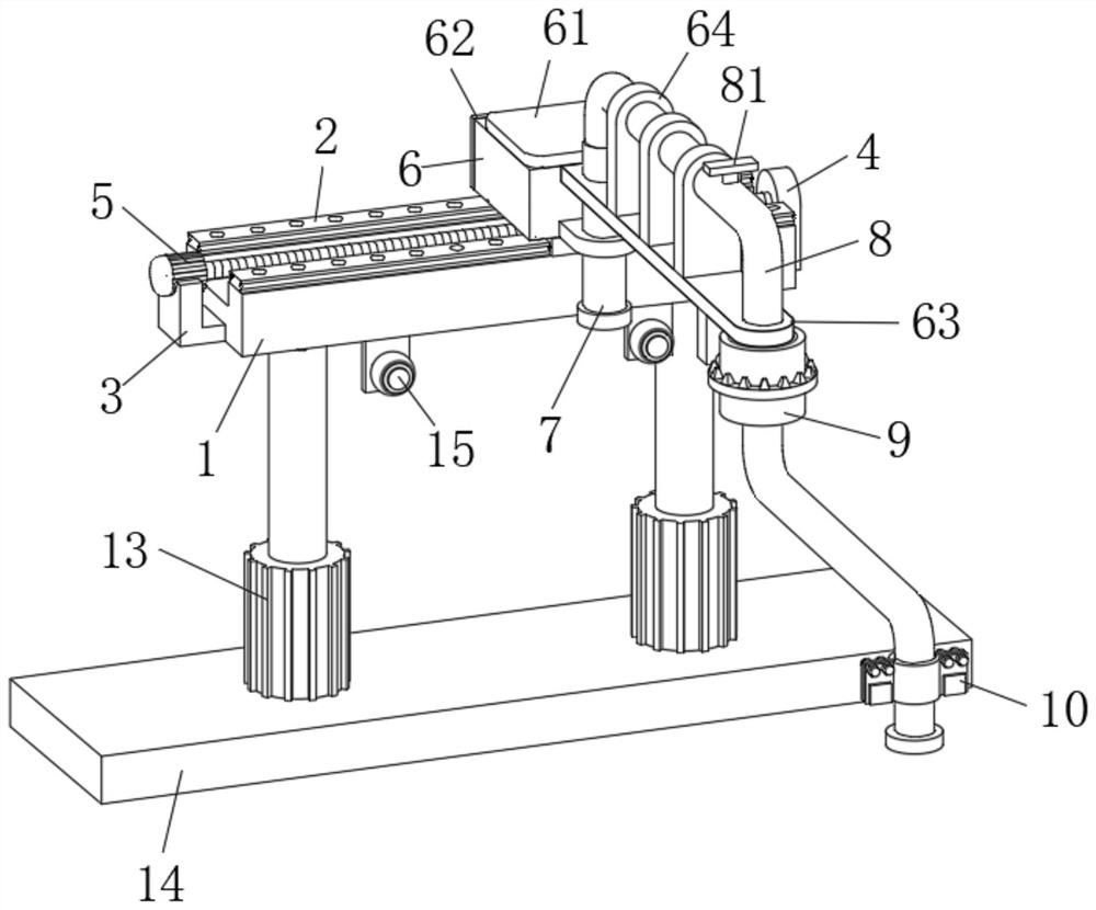
[0035] A 3D machine vision-based cantilever loading crane tube for trains, such as Figure 1-2 As shown, including the base 1, a slide rail 2 is fixedly welded on the upper front part and the upper rear part of the base 1, and a left fixed plate 3 and a right fixed plate 4 are respectively fixedly welded on the left end and the right end of the base 1. A driving assembly 5 is jointly arranged between the plate 3 and the right fixed plate 4, and a mobile platform 6 is jointly slidably connected between the two slide rails 2, and the mobile platform 6 is screwed together with the driving assembly 5, and the mobile platform 6 An industrial computer 61 is fixedly installed on the upper end, a control panel 62 is fixedly installed on the rear end of the mobile platform 6 , an extension plate 63 and a connecting seat 65 are fixedly installed on the front end of the industrial computer 61, and the connecting seat 65 is located on the extension plate 63 Below, the upper end of the ext...

Embodiment 2

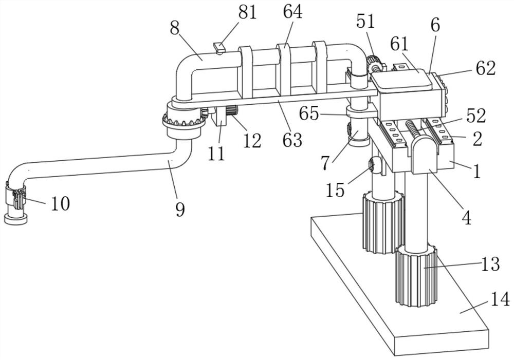
[0038] On the basis of Example 1, as Figure 3-5 As shown, a cantilever loading crane tube for trains based on 3D machine vision includes a base 1, a slide rail 2 is fixedly welded on the upper front part and the upper rear part of the base 1, and a slide rail 2 is fixedly welded on the left end and the right end of the base 1 respectively. A left fixed plate 3 and a right fixed plate 4, a driving assembly 5 is jointly arranged between the left fixed plate 3 and the right fixed plate 4, a mobile platform 6 is jointly slidably connected between the two slide rails 2, and the mobile platform 6 and the driving assembly 5 are screwed together, an industrial computer 61 is fixedly installed on the upper end of the mobile platform 6, a control panel 62 is fixedly installed on the rear end of the mobile platform 6, and an extension plate 63 and an extension plate 63 are fixedly installed on the front end of the industrial computer 61 A connection seat 65, and the connection seat 65 i...

Embodiment 3

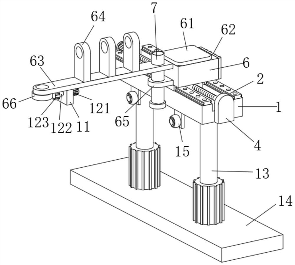
[0040] On the basis of Example 2, such as Figure 6-7 As shown, a cantilever loading crane tube for trains based on 3D machine vision includes a base 1, a slide rail 2 is fixedly welded on the upper front part and the upper rear part of the base 1, and a slide rail 2 is fixedly welded on the left end and the right end of the base 1 respectively. A left fixed plate 3 and a right fixed plate 4, a driving assembly 5 is jointly arranged between the left fixed plate 3 and the right fixed plate 4, a mobile platform 6 is jointly slidably connected between the two slide rails 2, and the mobile platform 6 and the driving assembly 5 are screwed together, an industrial computer 61 is fixedly installed on the upper end of the mobile platform 6, a control panel 62 is fixedly installed on the rear end of the mobile platform 6, and an extension plate 63 and an extension plate 63 are fixedly installed on the front end of the industrial computer 61 A connection seat 65, and the connection seat...


PUM


Abstract

The invention discloses a cantilever loading crane pipe for trains based on 3D machine vision. platform, and the mobile platform and the drive assembly are screwed together, an industrial computer is fixedly installed on the upper end of the mobile platform, a crane tube outer arm is arranged on the upper part of the crane tube inner arm, and the lower part of the side of the crane tube outer arm away from the crane tube inner arm runs through The lower end of the extension plate is movably connected with a crane tube mechanism, and one end of the stable plate is interspersed with a transmission mechanism. A surveillance camera. The cantilever loading crane tube for trains based on 3D machine vision of the present invention has high degree of automation, rapid and accurate positioning, low labor intensity, ensures the health of workers, is convenient to use, and can be widely used.

Description

technical field [0001] The invention relates to the technical field of equipment vision positioning, in particular to a 3D machine vision-based cantilever loading crane for trains. Background technique [0002] Crane tube: special equipment in the process of fluid loading and unloading in the petrochemical industry, also known as fluid loading and unloading arm, it is connected with a rotary joint and a rigid pipe and elbow to realize the transmission of liquid medium between trains, automobile tank cars and trestle storage and transportation pipelines The active equipment can replace the old-fashioned hose connection. It has the characteristics of high safety, flexibility and long life. The equipment can be widely used in the chemical industry and other industries to send and receive various liquid raw materials. [0003] The following problems exist in the use of ordinary cantilever cranes: 1. The labor intensity is high. During the loading process, the operator needs to ...

Claims


Application Information

Patent Timeline
Patent Type & Authority Patents(China)
IPC IPC(8): B67D7/42
CPCB67D7/42
Inventor 时东成刘园园徐洪立
Owner 连云港华恒石化设备制造有限公司
Why Eureka
Try Eureka