
Clinical debridement device in dermatology department

A dermatology and box technology, applied in the field of medical equipment debridement equipment, can solve the problems of poor flexibility, inability to adjust, and easy movement of patients' limbs, so as to reduce the difficulty of debridement, reasonable structural design, and convenient debridement care Effect

Inactive Publication Date: 2020-10-16
安丘市人民医院
View PDF0 Cites 6 Cited by
  • Summary
  • Abstract
  • Description
  • Claims
  • Application Information

AI Technical Summary

Problems solved by technology

[0003] At present, when medical personnel perform debridement on patients, they generally do not support the patient's affected limb. Not only is the debridement process extremely inconvenient, but also the patient's affected limb is easy to move, which affects debridement care; the structure of the existing dermatology debridement devices on the market is relatively Simple, the height of the injured limb support is fixed and cannot be adjusted, and it cannot be adjusted according to different patients or different situations, and the flexibility is poor; currently, when debridement is performed on patients, medical personnel use containers to take cleaning liquid to clean patients. The medicine liquid is easy to spill and cause waste when taking it, and the pouring volume is uneven, which affects the debridement effect on the patient; moreover, the waste liquid for cleaning the wound cannot be collected effectively, and the waste liquid splashes easily pollutes the environment

Method used


Image

  • Clinical debridement device in dermatology department
  • Clinical debridement device in dermatology department
  • Clinical debridement device in dermatology department

Examples


Embodiment 1

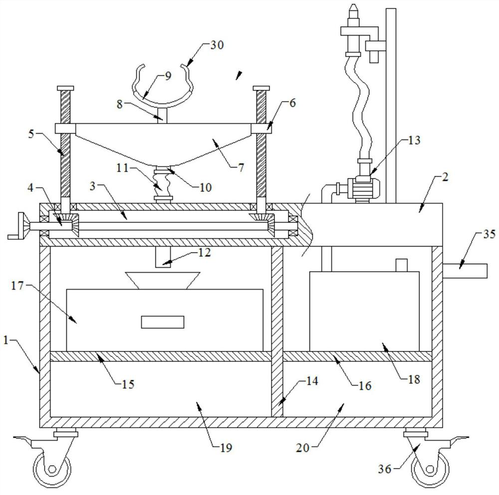
[0033] see figure 1 , 3, 4 and 6, this embodiment is a dermatological clinical debridement device, including a box body 1, a working platform 2 is arranged on the upper end of the box body 1, a cavity 3 is opened inside the working platform 2, and the interior of the cavity 3 is provided There is a transmission assembly 4, two screw rods 5 are rotatably connected to the upper wall of the cavity 3, a nut block 6 is screwed on the screw rod 5, and a liquid collecting tank 7 is fixedly connected between the nut blocks 6 on both sides. A support rod 8 is provided, the upper end of the support rod 8 is fixed with an arc-shaped support plate 9, the bottom of the liquid collecting tank 7 is connected with a liquid outlet pipe 10, and the lower end of the liquid outlet pipe 10 is connected with a first hose 11, and the first hose 11 is another One end is connected with a catheter 12 , the lower end of the catheter 12 penetrates the working platform 2 , the upper end of the right side...

Embodiment 2

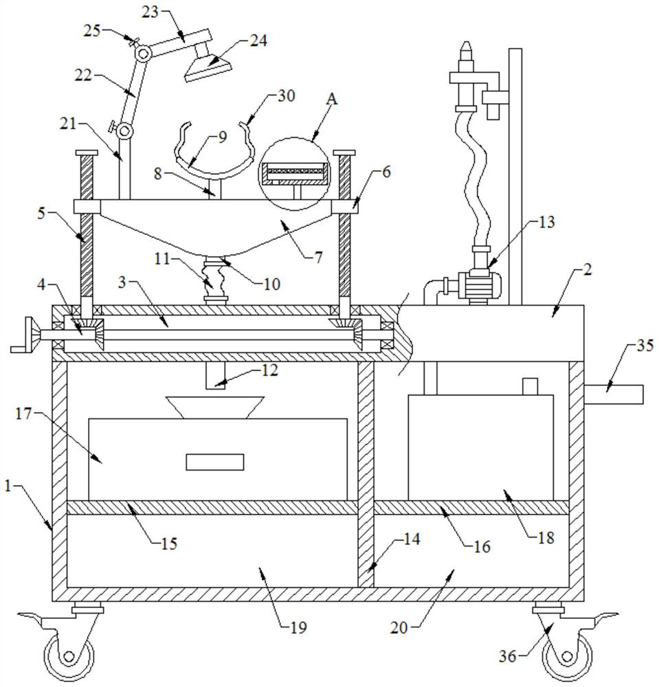
[0043] see figure 2 As shown, on the basis of Embodiment 1, a fixing rod 21 is fixedly connected to the upper end of the left wall of the liquid collecting tank 7, a first connecting rod 22 is hinged on the fixing rod 21, and a second connecting rod 23 is hinged on the upper end of the first connecting rod 22. , the lower end of the second connecting rod 23 is installed with a lighting lamp 24, and both ends of the first connecting rod 22 are provided with locking bolts 25.

[0044] When the light is not bright enough and the sight is not clear enough, it can be illuminated by turning on the lighting lamp 24, so that the medical staff can watch carefully, which can improve the effect of debridement. At the same time, the rotation angle of the first connecting rod 22 and the second connecting rod 23 can be adjusted to adjust the lighting angle of the lighting lamp 24, which is suitable for different situations on the site. Fixed and practical.

Embodiment 3

[0046] see figure 2 , 5 As shown, the upper end of the liquid collecting tank 7 is fixed with a pillar 26 at the front and rear, and the upper end of the pillar 26 is fixed with a placement slot 27. A placement screen 28 is installed inside the placement slot 27.

[0047] When the medical staff is debridement, the medical tools used can be placed on the placement screen 28 inside the placement tank 27, which is convenient for placement, and the residual liquid on the medical tools will flow down through the placement screen 28 into the liquid collection tank 7, Finally, it is collected in the liquid collecting tank 17, which can avoid that the medical tools are directly put aside, the waste liquid is likely to cause pollution, and the tools are inconvenient to be placed, so this structure has strong applicability.

[0048] The above-mentioned electrical components are all externally connected with a power supply, and the control methods thereof are common knowledge, so they ...


PUM


Abstract

The invention discloses a clinical debridement device in the dermatology department. The device comprises a box, a working platform is arranged at the upper end of the box, a transmission assembly isarranged in a cavity, a liquid collecting tank is fixedly connected between nut blocks on the two sides, supporting rods are arranged in front of and behind the upper end of the liquid collecting tank, arc-shaped supporting plates are fixedly connected to the upper ends of the supporting rods, and a spray washing assembly is arranged at the upper end of the right side of the working platform. Theliquid collecting tank and the arc-shaped supporting plates are driven by the transmission assembly to move up and down, the height of the arc-shaped supporting plates can be adjusted according to different patients and specific conditions, the flexibility is high, and the affected part can be cleaned by spraying a liquid by a spray washing head to the affected part of the patient; waste liquid after cleaning can fall into a liquid collecting box through the liquid collecting tank, the waste liquid can be collected, the environment is prevented from being polluted, and meanwhile, the illumination angle of a illumination lamp can be adjusted by adjusting the rotating angles of a first connecting rod and a second connecting rod; and medical tools used during debridement can be placed on a placement net plate in the placement groove, meanwhile, residual liquid on the medical tools can flow into the liquid collecting tank through the placement net plate, and the practicability is high.

Description

technical field [0001] The invention relates to the technical field of medical equipment debridement equipment, in particular to a dermatological clinical debridement device. Background technique [0002] Dermatology belongs to surgery and mainly treats various skin diseases. Common skin diseases include psoriasis, herpes, rosacea, impetigo, pyogenic infection, scars, ringworm, ichthyosis, underarm odor, acne, folliculitis, alopecia areata, Andrology, baby diaper rash, corns, freckles, sweat herpes, mite dermatitis, vitiligo, eczema, onychomycosis, scleroderma, itchy skin, oral care, hair removal, chloasma, etc. Clinical refers to the direct contact with the patient and the actual observation of the patient. The clinical department is the main body of the hospital, and it is directly responsible for the admission, diagnosis and treatment of patients; clinical personnel include doctors and nurses who directly participate in the treatment and care of patients; the medical tec...

Claims


Application Information

Patent Timeline
Patent Type & Authority Applications(China)
IPC IPC(8): A61G12/00A61M3/02
CPCA61G12/00A61M3/0254A61M3/0287A61M2205/587
Inventor 葛文涛周洪文李宗枝
Owner 安丘市人民医院
Learn More