Flexible traveling wave driven heart micropump and driving method thereof

A technology of sexual traveling wave and heart, which is applied in the field of flexible traveling wave driven cardiac micropump and its drive, which can solve the problem of affecting the service life of the device and the blood flow auxiliary index, the change of the outflow pressure aortic wall structure, and the change of blood composition, etc. problem, to achieve the effect of simple structure, easy miniaturization, and good speed control

Active Publication Date: 2020-10-16
JIANGSU UNIV
View PDF7 Cites 0 Cited by
  • Summary
  • Abstract
  • Description
  • Claims
  • Application Information

AI Technical Summary

Problems solved by technology

[0003] Thrombosis is likely to occur in the pump cavity gap and flow dead zone, which changes the blood composition and affects the service life of the device and the auxiliary blood flow index
Excessive suction is caused at the inlet of the pump chamber, leading to ventricular collapse, and the long-term high outflow pressure of the pump chamber causes changes in the wall structure of the aorta

Method used


Image

  • Flexible traveling wave driven heart micropump and driving method thereof
  • Flexible traveling wave driven heart micropump and driving method thereof
  • Flexible traveling wave driven heart micropump and driving method thereof

Examples


Embodiment Construction

[0030] Below in conjunction with accompanying drawing, technical scheme of the present invention is described in further detail:

[0031] Examples of described embodiments of the invention are shown in the drawings and should not be considered limited to the embodiments described herein. The embodiments described below by referring to the figures are exemplary and are intended to fully explain the scope of the present invention to those skilled in the art. In the drawings, components are exaggerated for clarity.

[0032] In describing the present invention, it is to be understood that the terms "central", "longitudinal", "transverse", "length", "width", "thickness", "upper", "lower", "axial", The orientation or positional relationship indicated by "radial", "vertical", "horizontal", "inner", "outer", etc. is based on the orientation or positional relationship shown in the drawings, and is only for the convenience of describing the present invention and simplifying the descrip...


PUM


Abstract

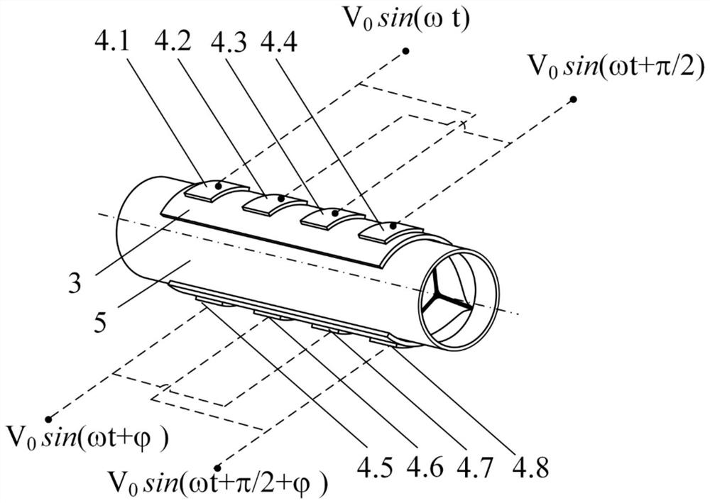
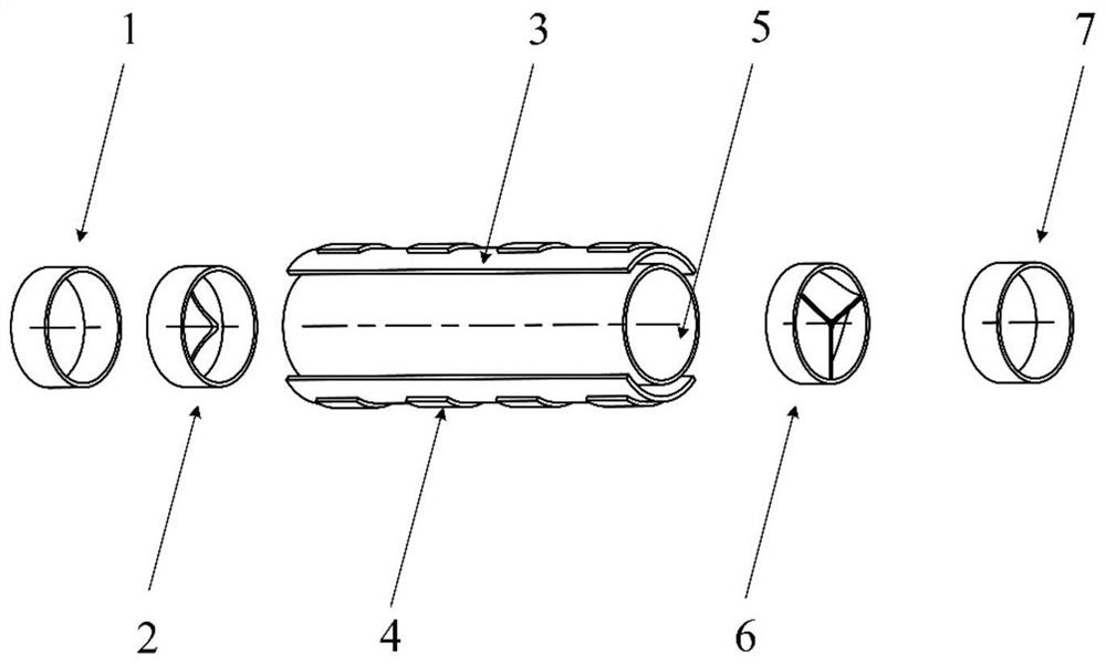
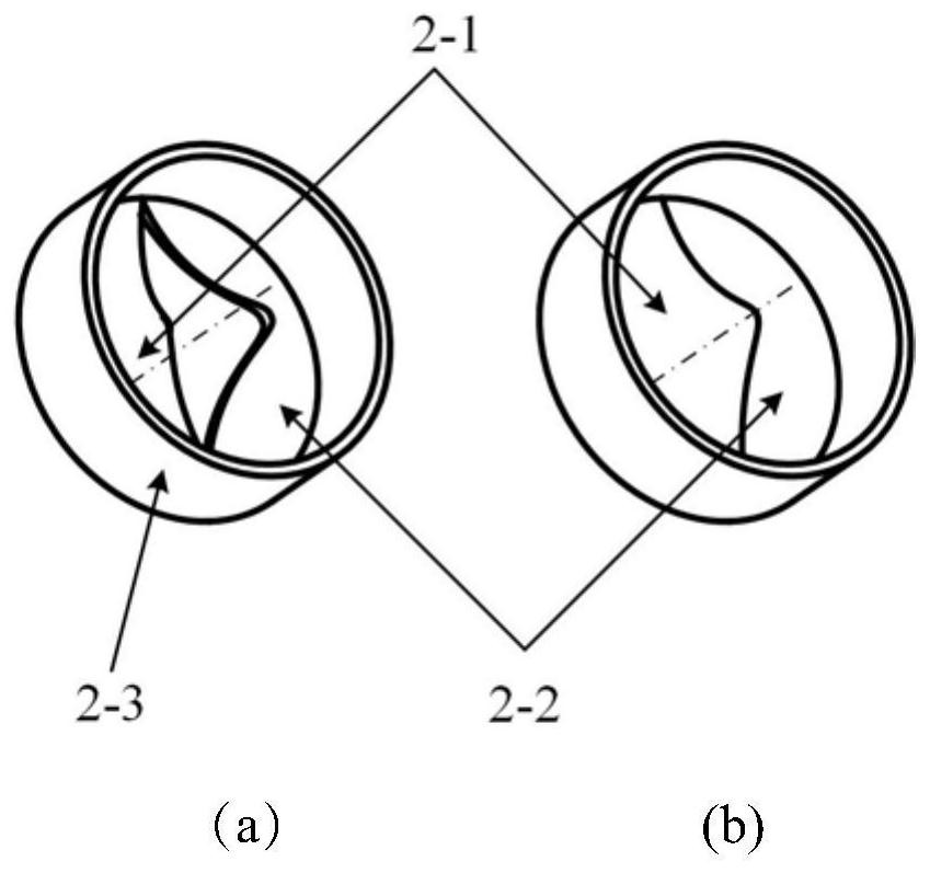
The invention discloses a flexible traveling wave driven heart micropump and a driving method thereof. The flexible traveling wave driven heart micropump comprises a pump body, a piezoelectric material, an elastic base body, a bionic three-flap valve, a two-flap valve, an inlet section and an outlet section, the piezoelectric materials are evenly disttendonuted on the two elastic base bodies, andthe two elastic base bodies are located on the upper wall face and the lower wall face of the pump body respectively. The two-flap valve is located at an inlet of the pump body, and the bionic three-flap valve is located at an outlet of the pump body. An electric signal with a phase difference is applied to the piezoelectric material, so that the elastic matrix drives the pump cavity to generate atraveling wave vibration mode, the volume change of the pump cavity and the opening and closing of the bionic three-flap valve and the bionic two-flap valve are caused, and blood in the cavity is pressed to directionally flow. During working, the shearing force between blood and the wall surface is low, hemolysis is avoided, no flow dead zone exists, the biocompatibility is good, and the high survival rate in the blood cell conveying process is guaranteed; cardiac contraction and diastole alternately is performed, and flow bionics is output; the driving part operates at extremely low noise, the speed controllability is good, and the blood supply requirements of patients under different organism metabolism and activity conditions can be met.

Description

technical field [0001] The invention belongs to the technical field of medical equipment, and specifically refers to a flexible traveling wave driven cardiac micropump and a driving method thereof. Background technique [0002] The commonly used vane-type artificial heart pump promotes blood circulation through the centrifugal force generated by the rotation of the impeller. The high-intensity shear stress generated by the high-speed rotation of the end of the impeller increases the mechanical damage of red blood cells and causes hemolysis; the inlet pressure of the impeller decreases and cavitation occurs. A large number of shock waves generated during the collapse around the cells damage the red blood cells and cause hemolysis, while generating noise and vibration. [0003] The pump chamber gap and flow dead zone are prone to thrombus, which changes the blood composition and affects the service life of the device and the blood flow auxiliary index. Excessive suction is ca...

Claims


Application Information

Patent Timeline
IPC IPC(8): A61M1/10
Inventor 黄俊李凯丛鑫港刘家铭
Owner JIANGSU UNIV
Why Eureka
Try Eureka