Dust and mist removal device for haze prevention and control

A defogging device and haze technology, applied in the field of ecological environmental protection, can solve problems such as affecting safe travel

Inactive Publication Date: 2020-10-20
张震震
View PDF8 Cites 3 Cited by
  • Summary
  • Abstract
  • Description
  • Claims
  • Application Information

AI Technical Summary

Problems solved by technology

[0005] The purpose of the present invention is to provide a dust and fog removal device for haze prevention and control that can quickly absorb the pollution particles in the haze air for the above-mentioned haze disasters that affect people's health and safe travel

Method used


Image

  • Dust and mist removal device for haze prevention and control
  • Dust and mist removal device for haze prevention and control
  • Dust and mist removal device for haze prevention and control

Examples


Embodiment 1

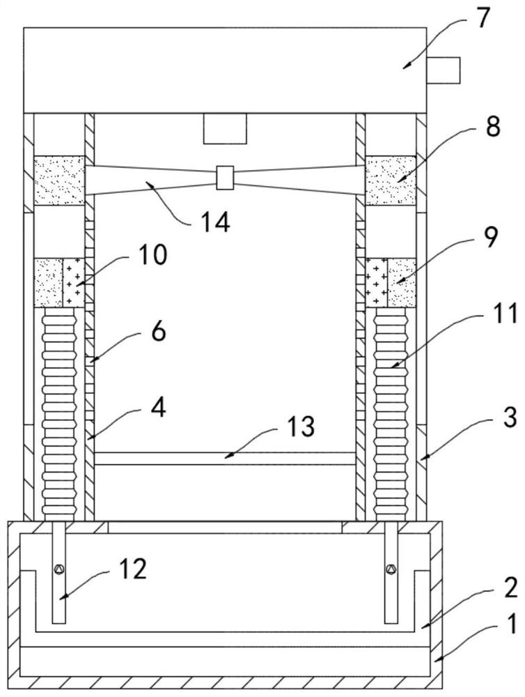
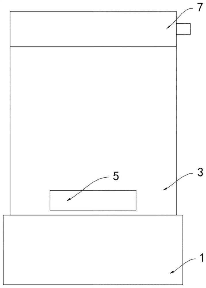
[0019] Such as Figure 1-3 As shown, a dust and fog removal device for haze prevention and control includes a base 1, a water storage tank 2 is installed in the base 1, a vertical cylinder 3 is installed on the upper end of the base 1, and the coaxial line in the cylinder 3 is An inner casing 4 is provided, and both the inner casing 4 and the cylinder body 3 are fixedly communicated with the base 1, and the lower side walls of the inner casing 4 and the cylinder body 3 are provided with exhaust holes 5 communicating with the outside, and the cylinder body 3 A plurality of microholes 6 are equidistantly arranged on the side wall of the cylinder body 3, and a fan 7 is installed on the upper end of the cylinder body 3, and the air outlet of the fan 7 extends to the inner casing 4 to be arranged.

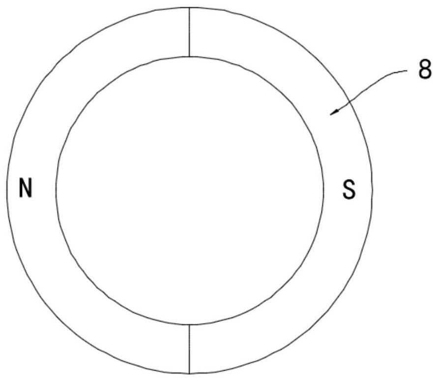
[0020] A fan 14 is rotatably connected to the inner side wall of the inner housing 4, and a permanent magnetic ring 8 rotates between the inner housing 4 and the cylinder body 3. The ou...

Embodiment 2

[0025] Such as Figure 4 As shown, the difference between this embodiment and Embodiment 1 is that the lower end of the water storage tank 2 is fixedly connected to the inner bottom surface of the base 1 through the support spring 18, and the lower contact 15 is fixedly connected to the side wall of the upper end of the water storage tank 2. An upper contact 16 is installed on the inner top surface of the base 1 , and a refrigerating sheet 17 is installed on the inner wall of the inner housing 4 , and the refrigerating sheet 17 is electrically connected to an external power source through the upper contact 16 and the lower contact 15 in turn.

[0026] In this embodiment, during the long-term circulation of the soapy liquid in the water storage tank 2, the moisture in the soapy liquid evaporates and decreases. , to push the water storage tank 2 to move upwards. At this time, the upper contact 16 is in contact with the lower contact 15, and the cooling sheet 17 is connected with...


PUM


Abstract

The invention belongs to the technical field of ecological environmental protection, and especially relates to a dust and mist removal device for haze prevention and control. The device includes a base, a water storage tank is mounted in the base, and a vertically-arranged barrel is installed at the upper end of the base. An inner shell is coaxially arranged in the barrel; the inner shell and thebarrel are fixedly communicated with the base; exhaust holes communicated with the outside are formed in the side walls of the lower ends of the inner shell and the barrel; and a plurality of micropores are formed in the side wall of the barrel at equal intervals, a draught fan is installed at the upper end of the barrel, an air outlet of the draught fan extends into the inner shell, a fan is rotationally connected to the inner side wall of the inner shell, and a permanent magnet ring is rotationally arranged between the inner shell and the barrel. Soap bubbles can be generated in the inner shell through airflow flowing, the surface area of the soap bubbles is large, the soap bubbles make full contact with haze gas, particles such as particles, dust and aerosol in the haze gas are effectively adsorbed, the good dust and mist removal effect is achieved, and haze prevention and control are facilitated.

Description

technical field [0001] The invention belongs to the technical field of ecology and environmental protection, and in particular relates to a dust and fog removal device for haze prevention and control. Background technique [0002] Haze is PM2.5 and other size particles, dust, aerosols and other particles floating in the atmosphere. Haze weather is mainly caused by extensive development methods, unreasonable industrial structure and energy structure. The root cause is still fossil energy. One is Coal burning, one is fuel oil, and the other is relatively extensive development, which emits a large amount of pollutants. The emergence of smog disasters is the result of long-term atmospheric pollution. [0003] Smog disasters often occur in heavily polluted cities. Smog disasters not only affect people's health, and even cause respiratory diseases in severe cases, but also hinder people's normal travel. Visibility is low in smog weather. One of the major causes of traffic acciden...

Claims


Application Information

Patent Timeline
Patent Type & Authority Applications(China)
IPC IPC(8): B01D47/04
CPCB01D47/04
Inventor 张震震李燕玲
Owner 张震震
Why Eureka
Try Eureka