
Control Method of Forging Deformation of Complicated Disc-type Die Forgings

A control method and technology of deformation amount, applied in the field of forging technology, can solve the problem of large design amount of remaining forging pieces, and achieve the effects of reducing raw materials, reducing forging cost, and increasing deformation amount

Active Publication Date: 2022-06-07
SICHUAN ENG TECHN COLLEGE +1
View PDF0 Cites 0 Cited by
  • Summary
  • Abstract
  • Description
  • Claims
  • Application Information

AI Technical Summary

Problems solved by technology

[0004] The present invention aims at the problem that in the existing forging process of complex pancake type die forgings, in order to ensure the deformation amount of the part area in the forging, the design amount of the remaining pieces of the forging is relatively large, and provides a method for controlling the forging deformation amount of complex pancake type die forgings

Method used


Image

  • Control Method of Forging Deformation of Complicated Disc-type Die Forgings
  • Control Method of Forging Deformation of Complicated Disc-type Die Forgings
  • Control Method of Forging Deformation of Complicated Disc-type Die Forgings

Examples


Embodiment 1

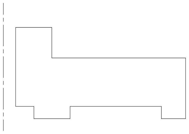
[0061] Forged by die forging process Figure 1a The parts shown in are described as examples, as follows:

[0062] Figure 1a The part shown in is a disc-shaped part with the dotted line as the center of rotation.

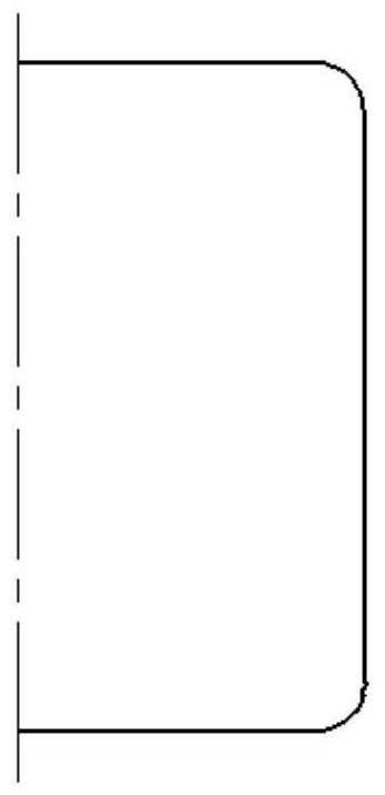
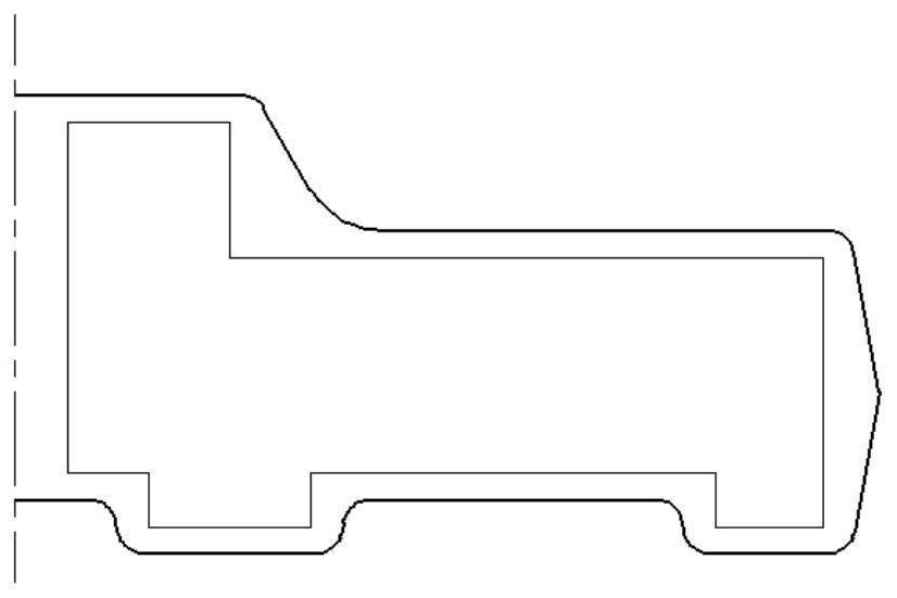
[0063] like Figure 1a , Design the final forging model according to the part drawing according to the principle of small margin design (make the forging model as close to the part as possible, and make the forging size as small as possible), such as Figure 1c ; Design the prefabricated model according to the principle of easy forming and no need for machining, such as Figure 1b .

[0064] Based on the designed forging model and preform model, numerical simulation is carried out in deform software to simulate the deformation process from the preform model to the final forging model, analyze the deformation of each area of ​​the forging during forming, and determine the part in the forging process. The areas with insufficient deformation during forming are lo...

Embodiment 2

[0076] Forged by die forging process Figure 4a The parts shown in are described as examples, as follows:

[0077] Figure 4a The part shown in is a disc-shaped part with the dotted line as the center of rotation.

[0078] like Figure 4a , according to the part drawing, the final forging model is designed according to the principle of small margin design, such as Figure 4c ; Design the prefabricated model according to the principle of easy forming and no need for machining, such as Figure 4b .

[0079] Based on the designed forging model and preform model, numerical simulation is carried out in deform software to simulate the deformation process from the preform model to the final forging model, analyze the deformation of each area of ​​the forging during forming, and determine the part in the forging process. The areas with insufficient deformation during forming are located in the upper left and lower left corners of the forging, such as Figure 4d , the deformation...


PUM


Abstract

The invention discloses a method for controlling the amount of forging deformation of a complex plate-type die forging. By setting a step structure on the preform model and the final forging model, when the forging is formed, the corresponding step structure of the final forging forming mold and the preform The step structure set on the model forms two or more deformation fulcrums at the corresponding step structure positions between the final forging forming die and the preform; by setting multiple deformation fulcrums in the insufficiently deformed area, the prefabrication can be greatly increased. The amount of deformation in the area where the deformation amount is insufficient during billet forming can greatly reduce the design amount of the remaining block of the forging while ensuring the amount of deformation during the forming process of the forging, reducing the raw materials required for forging forging and reducing the forging cost.

Description

technical field [0001] The invention relates to the technical field of forging technology, in particular to a method for controlling the forging deformation of a complex pancake inner die forging. Background technique [0002] In order to meet the weight reduction requirements of aerospace force-bearing parts, in recent years, aerospace pancake force-bearing parts are increasingly designed as complex integral parts. This kind of pancake integral parts not only have complex shapes, but also require no less than ordinary shape parts for their microstructure and macroscopic mechanical properties. In order to ensure that the complex pancake integral parts meet the requirements in terms of microstructure and macroscopic mechanical properties, in the process of designing and forging corresponding integral forgings, especially in the process of forging complex pancake forgings of titanium alloys and superalloys, it is generally necessary to Strictly control the uniformity of the d...

Claims


Application Information

Patent Timeline
Patent Type & Authority Patents(China)
IPC IPC(8): B21J1/00B21K1/32
CPCB21J1/003B21K1/32
Inventor 刘国标王周田张鹏单丽梅王泽忠李海荣
Owner SICHUAN ENG TECHN COLLEGE
Learn More