Grouting structure capable of filling soluble crystal and construction method

A construction method and grouting technology, which can be used in basic structure engineering, excavation, soil protection, etc., and can solve problems such as difficulty in controlling grouting pressure, failure of negative pressure drainage, etc.

Active Publication Date: 2020-10-20
CHINA RAILWAY ERYUAN ENG GRP CO LTD
View PDF4 Cites 6 Cited by
  • Summary
  • Abstract
  • Description
  • Claims
  • Application Information

AI Technical Summary

Problems solved by technology

[0005] The purpose of the present invention is to overcome the above-mentioned shortcomings that the existing negative pressure drainage technology is difficult to control ...

Method used


Image

  • Grouting structure capable of filling soluble crystal and construction method
  • Grouting structure capable of filling soluble crystal and construction method

Examples


Embodiment 1

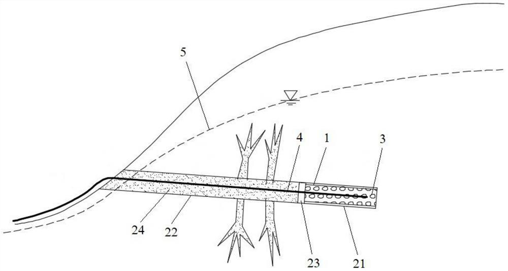
[0037] Such as figure 1 As shown, a grouting structure filled with soluble crystals according to the present invention includes a permeable section 21 and a grouting section 22, a water-stop member 23 is arranged between the permeable section 21 and the grouting section 22, and the permeable The section 21 is provided with a permeable pipe 1 filled with solid soluble crystals 3, and the permeable section 21 is provided with a water inlet of a drainage pipe 4, and the elevation of the water inlet of the drainage pipe 4 is higher than The elevation of the water outlet of the drain pipe 4, the head of the drain pipe 4 is less than the height of the water column corresponding to the local atmospheric pressure.

[0038] Specifically, the diameter of the borehole should be greater than 90 mm. The permeable pipe 1 can be a perforated corrugated pipe with outer woven filter cloth and inner support HDPE, which can prevent large particles such as coarse sand and gravel from entering. Th...

Embodiment 2

[0041] A construction method of a grouting structure filled with soluble crystals according to the present invention adopts a grouting structure filled with soluble crystals as described in Example 1, comprising the following steps:

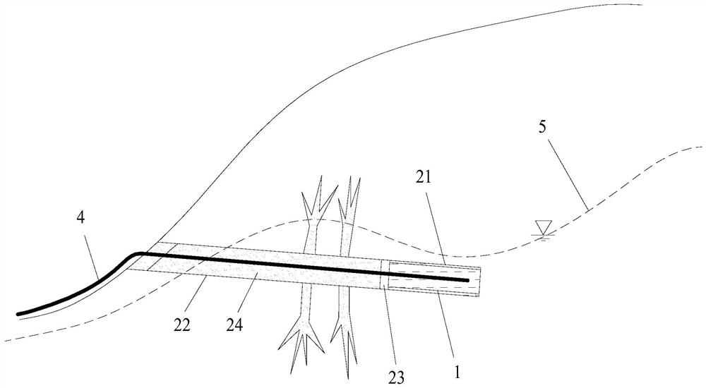
[0042] a. According to the geological survey, drill a downwardly inclined borehole, and make the permeable section 21 of the borehole be located below the groundwater level 5 controlled by the slope; The position of section 21, the height difference between the bottom of the borehole and the opening of the borehole is less than the height of the water column corresponding to the local atmospheric pressure, so as to ensure that the lift of the drain pipe 4 meets the requirements;

[0043] b. Set the permeable pipe 1 in the permeable section 21, and then insert the drain pipe 4 in the permeable pipe 1, so that the port of the drain pipe 4 goes deep into the bottom of the permeable pipe 1;

[0044] c. Fill the water-permeable pipe 1 with solid solub...


PUM

PropertyMeasurementUnit
Diameteraaaaaaaaaa

Abstract

The invention discloses a grouting structure capable of filling a soluble crystal and a construction method. The structure comprises a water permeating section and a grouting section, wherein a water-stop component is arranged between the water permeating section and the grouting section; a water permeating tube is arranged in the water permeating section; the solid-state soluble crystal is filledin the water permeating section; a water inlet of a water drainage tube is arranged in the water permeating section; and elevation of the water inlet of the water drainage tube is greater than that of the water outlet of the water drainage tube. The grouting structure is beneficial for increasing grouting pressure, reduces cracks of the grouting section, and improves sealing effect, so that negative-pressure effect of the water permeating section is improved; during grouting, the water-stop component can be effectively supported, and slurry is prevented from entering the water permeating section to disturb formation of a negative-pressure environment, so that blockage of the water permeating tube is avoided, the water-stop component is prevented from greater displacement as a result of extrusion, and continuous water drainage effect of a slope deep layer is favorably guaranteed, and therefore, the grouting structure is of great significance on solving the water drainage and control problem of a large slope.

Description

technical field [0001] The invention relates to the technical field of slope drainage engineering, in particular to a grouting structure filled with soluble crystals and a construction method. Background technique [0002] Rainfall infiltration is one of the important factors that change the mechanical parameters of slopes and induce landslides. Timely and effective drainage of slopes is an effective way to solve this problem. The existing slope drainage measures mainly include: surface drainage ditch and blind drainage ditch, water collection well pumping, horizontal drainage holes, underground drainage holes, negative pressure drainage technology, etc. [0003] The existing slope negative pressure drainage technology mainly divides the slope drilling into a permeable drilling section and a grouting sealing drilling section, and a water-expandable rubber water-stop ring is arranged between the two, as described in Chinese Patent Publication No. CN107246019A A self-starting...

Claims


Application Information

Patent Timeline
IPC IPC(8): E02D15/00
CPCE02D15/00E02D17/20E02D5/80E02D3/10E02D15/04E02D19/10
Inventor 范雲鹤郑长青喻渝赵万强孙红月胖涛曹彧谭永杰刘金松刘洋尚岳全帅飞翔琚国全蒋立
Owner CHINA RAILWAY ERYUAN ENG GRP CO LTD
Why Eureka
Try Eureka