Miniature patch antenna
A patch antenna, miniature technology, applied in the field of antennas, can solve the problems of large antenna size and unfavorable application, etc.
- Summary
- Abstract
- Description
- Claims
- Application Information
AI Technical Summary
Problems solved by technology
Method used
Image
Examples
Embodiment 1
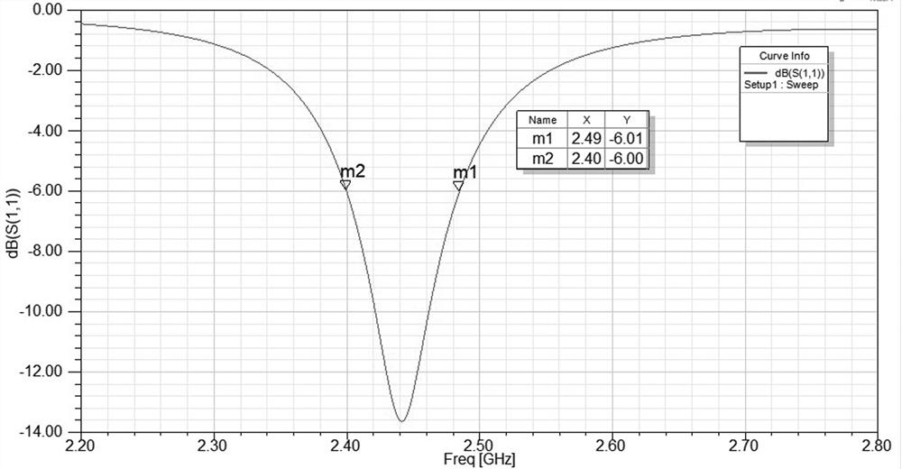
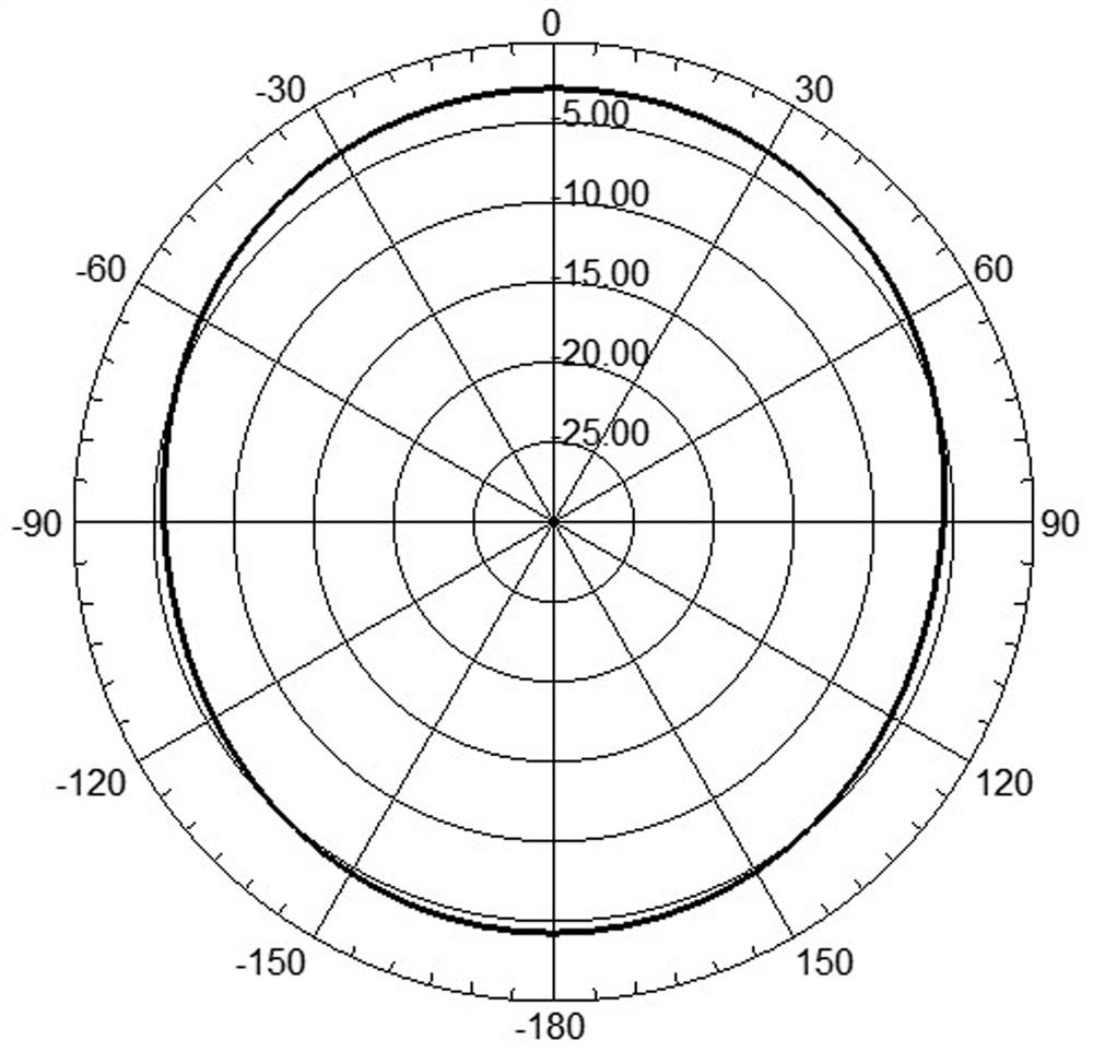
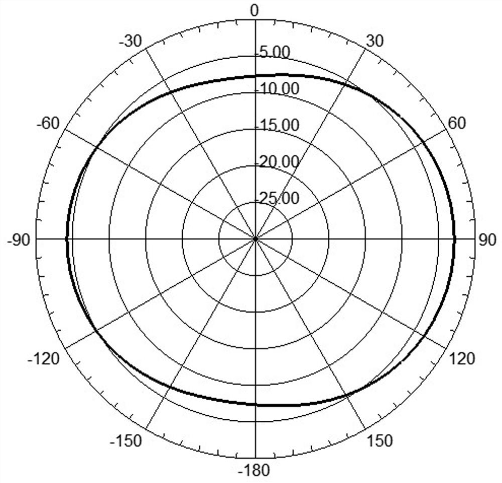
[0056] Such as Figure 1~3 As shown, this embodiment shows a miniature patch antenna, which includes an FR4 dielectric substrate 100, a folded line radiation patch 200 located on the front side of the FR4 dielectric substrate 100, an edge front loading unit 400 and a feeder 300, and The edge backside loading unit 600 located on the backside of the FR4 dielectric substrate 100, the size of the miniature patch antenna is designed to be 5mm*5mm, which is printed at the relative permittivity ε r =4.4, loss tangent tanδ =0.02 on the FR4 dielectric substrate 100, the size of the FR4 dielectric substrate 100 is 20mm*20mm*1mm, that is, the micro-patch antenna is formed on the 5mm*5mm spacer 110 separated by the FR4 dielectric substrate 100, The outside of the spacer 110 is the ground plane of the dielectric substrate 100. It can be understood that when the antenna is formed by a printing process, the spacer 110 is a blank area before the miniature patch antenna is formed, that is, ...
PUM
 Abstract
Description
Claims
Application Information
 - R&D
- Intellectual Property
- Life Sciences
- Materials
- Tech Scout
- Unparalleled Data Quality
- Higher Quality Content
- 60% Fewer Hallucinations
Browse by: Latest US Patents, China's latest patents, Technical Efficacy Thesaurus, Application Domain, Technology Topic, Popular Technical Reports.
© 2025 PatSnap. All rights reserved.Legal|Privacy policy|Modern Slavery Act Transparency Statement|Sitemap|About US| Contact US: help@patsnap.com


