
Automatic feeding device for photovoltaic fishpond and using method of automatic feeding device

A fish pond, automatic technology, applied in application, fish farming, agricultural fishing, etc., can solve the problems of feed scattered under the photovoltaic panel, easy to concentrate somewhere, uneven artificial feeding, etc.

Active Publication Date: 2020-10-23
SHANDONG AUCLON SOLAR ENERGY TECH
View PDF21 Cites 2 Cited by
  • Summary
  • Abstract
  • Description
  • Claims
  • Application Information

AI Technical Summary

Problems solved by technology

[0003] Nearly 75% of the water in the photovoltaic fishpond is blocked by photovoltaic panels, and the temperature of the waters covered by photovoltaic panels is relatively low, which can effectively solve the problem of poor appetite of fish caused by high temperature, but it is also because of the photovoltaic panels. As a result, it is difficult to scatter feed under the photovoltaic panels in the current manual feeding method, which often requires personnel to row boats to enter under the photovoltaic panels. Under the influence of dense photovoltaic brackets, artificial feeding will be uneven, making fish easy to concentrate Somewhere, it is easy for fish to be injured due to collisions when eating, and the photovoltaic support is easily damaged by collision for a long time under the influence of personnel and fish, which affects the service life of the photovoltaic support

Method used


Image

  • Automatic feeding device for photovoltaic fishpond and using method of automatic feeding device
  • Automatic feeding device for photovoltaic fishpond and using method of automatic feeding device
  • Automatic feeding device for photovoltaic fishpond and using method of automatic feeding device

Examples


Embodiment Construction

[0026] The following examples are for illustrative purposes only and are not intended to limit the scope of the invention.

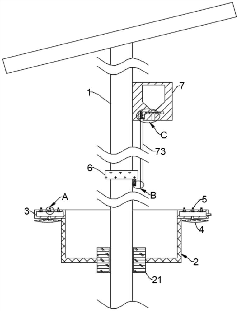
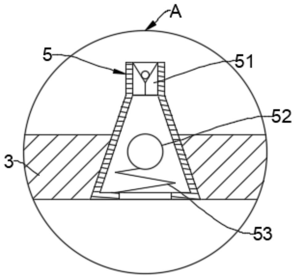
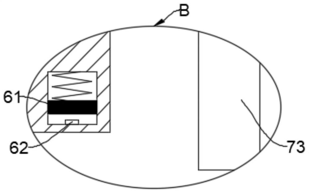
[0027] Such as Figure 1-4 As shown, an automatic feeding device for a photovoltaic fish pond and its use method include a photovoltaic support 1 arranged in the pond, and the photovoltaic support 1 is provided with a barrier sleeve 2 that can slide up and down along the photovoltaic support 1 .

[0028] The barrier sleeve 2 is a filter mesh structure, and the barrier sleeve 2 is provided with a plurality of mesh holes with a diameter of 3 cm, which can prevent large fish from passing through the barrier sleeve 2, and ensure that small fish can pass through the barrier sleeve 2, thereby preventing the fish from passing through the barrier sleeve 2. Big fish and small fish have the effect of separating.

[0029] The bottom end of the barrier sleeve 2 is slidably connected to the photovoltaic support 1 through a magnetic ring 21 , and the top end of the b...


PUM


Abstract

The invention belongs to the field of fishery breeding, and particularly relates to an automatic feeding device for a photovoltaic fishpond and a using method of the automatic feeding device. The automatic feeding device comprises a photovoltaic support arranged in the pond; a blocking sleeve capable of sliding up and down along the photovoltaic support is arranged on the photovoltaic support; thetop end of the blocking sleeve is fixedly connected with an air blowing ring capable of blowing air to the pond; the bottom end of the air blowing ring communicates with a plurality of air bags; thetop end of the air blowing ring is provided with a plurality of spray heads capable of being controlled to be opened or closed according to air pressure changes; the photovoltaic support is provided with a fish luring lamp controlled by the blocking sleeve to work; and the photovoltaic support is provided with a feeding box controlled by the blocking sleeve to conduct feeding. The two problems oflow dissolved oxygen content in the photovoltaic fishpond due to reduction of aquatic plants and influence on growth of small fishes due to the fact that the small fishes have difficulty in obtainingfood can be solved at the same time by utilizing changes of air flow and pressure intensity.

Description

technical field [0001] The invention belongs to the field of fish farming, and in particular relates to an automatic feeding device for photovoltaic fish ponds and an application method thereof. Background technique [0002] Photovoltaic fish pond is a method of fish farming using fishery and light complementarity. Fishery and light complementation refers to the combination of fish farming and photovoltaic power generation. A photovoltaic panel array is erected above the water surface of the fish pond, and fish and shrimp can be cultivated in the water below the photovoltaic panel. , Photovoltaic arrays can also provide good shelter for fish farming, forming a new power generation model of "power generation from the top and fish farming from the bottom". [0003] Nearly 75% of the water in the photovoltaic fishpond is blocked by photovoltaic panels, and the temperature of the waters covered by photovoltaic panels is relatively low, which can effectively solve the problem of ...

Claims


Application Information

Patent Timeline
IPC IPC(8): A01K61/80A01K63/04
CPCA01K61/80A01K63/042Y02A40/81Y02P60/60
Inventor 艾保英
Owner SHANDONG AUCLON SOLAR ENERGY TECH
Learn More