Medical waste treatment device based on compression crushing treatment technology

A technology of medical waste and treatment equipment, which is applied in the field of medical waste treatment equipment based on compression and pulverization treatment technology, which can solve the problems of inability to sterilize medical waste, endanger the personal safety of operators, and high risk

Pending Publication Date: 2020-10-23
YIKANG TECH CO LTD
View PDF0 Cites 6 Cited by
  • Summary
  • Abstract
  • Description
  • Claims
  • Application Information

AI Technical Summary

Problems solved by technology

However, the existing medical waste crushing mechanism is very simple, can only perform simple crushing operations, and cannot sterilize medical waste, resulting in the exposure of a large number of germs during the crushing process, which is very dangerous and endangers the operation. personal safety

Method used


Image

  • Medical waste treatment device based on compression crushing treatment technology
  • Medical waste treatment device based on compression crushing treatment technology
  • Medical waste treatment device based on compression crushing treatment technology

Examples


Embodiment 1

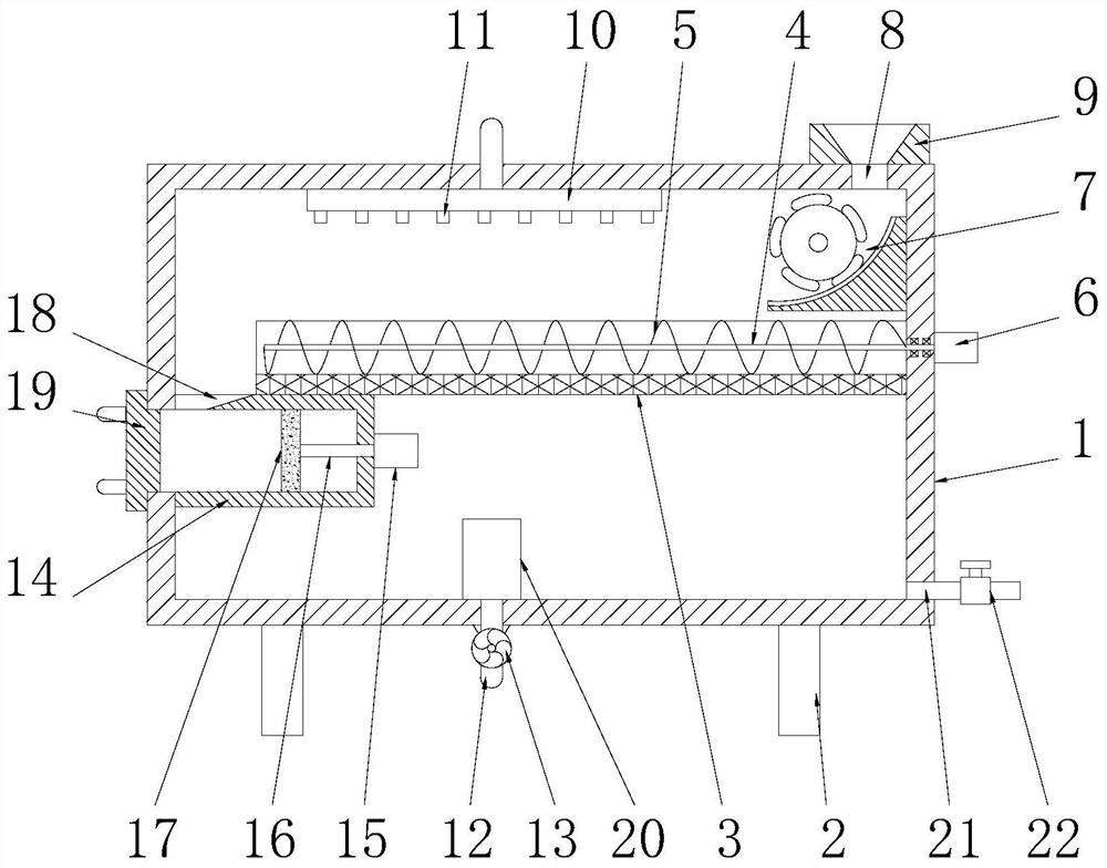
[0024] See figure 1, a medical waste treatment device based on compression crushing treatment technology, including a casing 1, the casing 1 is a cylindrical structure, the bottom of the casing 1 is uniformly provided with a number of legs 2, and the bottom of the casing 1 The middle part of the inner cavity is provided with a transmission grid slot 3, and the end of the transmission grid slot 3 is fixedly connected to the inner cavity wall of the casing 1. The transmission grid slot 3 is made of metal mesh. The cross section of the transmission grid slot 3 It is a semi-circular structure, and a transmission shaft 4 is arranged in the transmission mesh tank 3, the axis of the transmission mesh groove 3 coincides with the axis of the transmission shaft 4, and the end of the transmission shaft 4 penetrates the side wall of the casing 1 and is connected in rotation On the feed motor 6, the transmission shaft 4 is rotatably connected to the casing 1, the feed motor 6 is fixedly in...

Embodiment 2

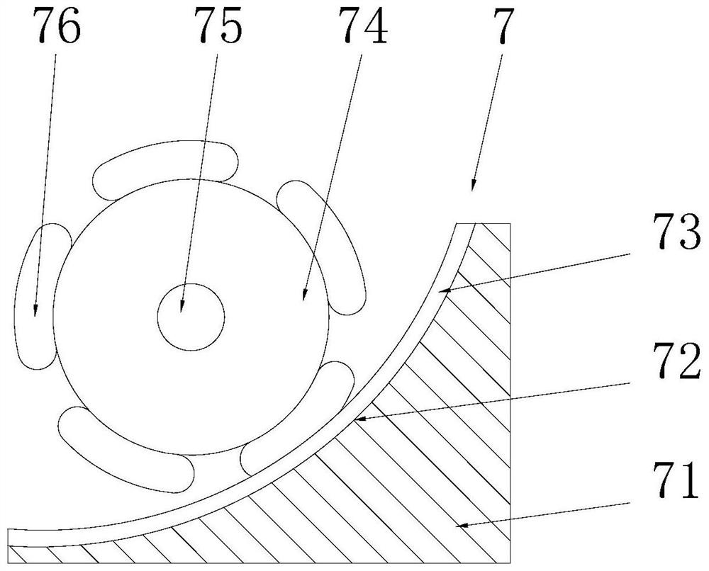
[0028] See figure 2 The difference from Embodiment 1 is that the crushing mechanism 7 includes a crushing seat 71 and a crushing roller 74, the crushing seat 71 is fixedly installed on the inner cavity side wall of the casing 1, and the left end of the crushing seat 71 is provided with There are crushing surfaces 72 matched with the crushing roller 74 and the feeding hole 8 respectively, the crushing surface 72 is an arc surface, and several fixed blades 73 are uniformly arranged on the crushing surface 72, and the fixed blades 73 are arc blades. The crushing roller 74 is arranged on the left side of the crushing surface 72, and the crushing roller 74 is rotatably connected to the casing 1 through the crushing shaft 75, and one end of the crushing shaft 75 penetrates the side wall of the casing 1 and is rotatably connected to the external motor (not shown in the figure), the outer circular surface of the crushing roller 74 is evenly provided with some movable blades 76 that m...

Embodiment 3

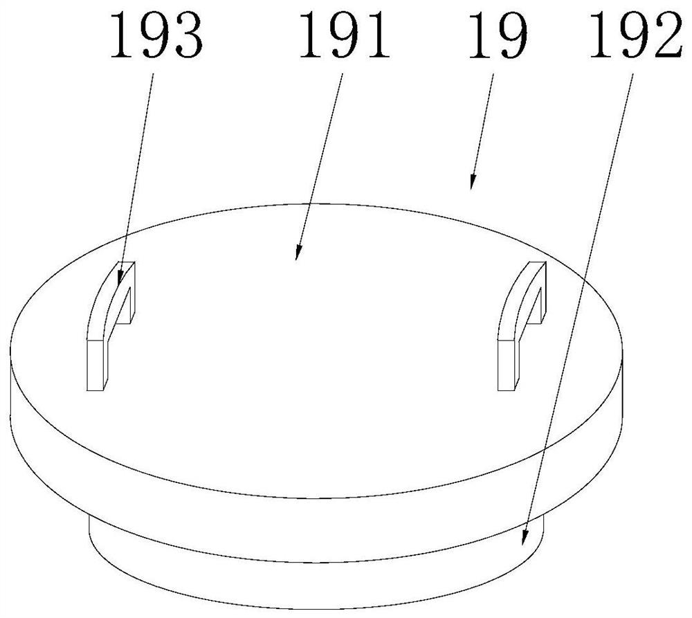
[0030] See image 3 The difference from Embodiment 1 is that the sealing cover 19 includes a cover body 191, the bottom end of the cover body 191 is fixedly connected with a sealing boss 192 matched with the discharge cylinder 14, and the cover body 191 and the sealing boss The posts 192 are integrally formed, and the sealing convex post 192 is screwed to the discharge cylinder 14. The top of the cover body 191 is symmetrically provided with handrails 193. The handrails 193 are U-shaped structures. The handrail 193 rotates the cover 191, and then rotates the sealing boss 192, so that the sealing boss 192 can seal or open the discharge barrel 14, so as to ensure the forming, processing and discharging of medical waste fragments, which can greatly improve the convenience of the whole device application .


PUM


Abstract

The invention discloses a medical waste treatment device based on a compression crushing treatment technology. The medical waste treatment device comprises a machine shell, a conveying net groove is formed in the middle of an inner cavity of the machine shell, a conveying shaft is arranged in the conveying net groove, the outer side of the conveying shaft is sleeved with a conveying auger matchedwith the conveying net groove, a crushing mechanism is arranged on the right side of the upper portion of the conveying net groove, a feeding hole matched with the crushing mechanism is connected to the right side of the top end of the machine shell in a penetrating mode, and a discharging barrel is fixedly connected to the left side of the bottom end of the conveying net groove. According to thedevice, disinfectant at the bottom of the inner cavity of the machine shell is pumped through a circulating pump, so that disinfectant is injected into a spraying device through a circulating pipe andfinally sprayed out through a nozzle, disinfectant is sprayed to medical waste fragments in the conveying net groove, and disinfection treatment is conducted on the medical waste fragments, so that alarge number of germs are effectively prevented from being exposed in the medical waste crushing process, the production safety of medical waste crushing can be improved to the maximum extent, and therefore the personal safety of operators is guaranteed.

Description

technical field [0001] The invention relates to the technical field of medical waste processing, in particular to a medical waste processing device based on compression crushing processing technology. Background technique [0002] Medical waste refers to directly or indirectly infectious, toxic and other hazardous waste produced by medical and health institutions in the course of medical treatment, prevention, health care and other related activities. Hospital waste refers to all the waste that needs to be discarded and cannot be reused in the hospital, including biological and non-biological, as well as domestic waste. Medical waste refers to the waste generated during the process of diagnosis, treatment, nursing and other activities of patients. Medical waste may contain a large number of pathogenic microorganisms and harmful chemicals, and even radioactive and damaging substances. Therefore, medical waste is an important risk factor that causes disease transmission or re...

Claims


Application Information

Patent Timeline
Patent Type & Authority Applications(China)
IPC IPC(8): B09B3/00B09B5/00B02C18/14B02C18/18B02C18/22B30B9/30A61L11/00A61L2/18A61L2/26B01D29/03B01D29/56
CPCA61L2/18A61L2/26A61L11/00B01D29/03B01D29/56B02C18/14B02C18/18B02C18/2216B02C2201/06B09B3/0075B09B5/00B30B9/301B30B9/3057
Inventor 丁宇曲毅郝进伟杨宏旺刘雪徐慧荟张华巍王兆选张培杨谢辉李守伟曹贻社于海深常安金田宗康琦李鹏梁春花柳晓明马吉飞牟玉明裴俊玲任国杰杨建成宋晓琳孙国剑王翠辉吴晓峰刘丽肖洪钢武伟臧岐山张广为张来君赵伟龙李楠郑勇王昌启冯平
Owner YIKANG TECH CO LTD
Why Eureka
Try Eureka