Beam column splicing joint

A joint, beam-column technology, applied in the field of building structure, can solve problems such as time-consuming, difficult application, lack of penetration, etc.

Inactive Publication Date: 2020-10-23
XI'AN UNIVERSITY OF ARCHITECTURE AND TECHNOLOGY
View PDF4 Cites 3 Cited by
  • Summary
  • Abstract
  • Description
  • Claims
  • Application Information

AI Technical Summary

Problems solved by technology

Welding process There is always welding residual stress after welding. At the same time, due to the rapid cooling of the heat-affected zone of the welded parts, under the condition of high carbon content, it is easy to produce quenched martensite and cracks; the control is not in place during the welding process, Pores, slag inclusions, lack of fusion, lack of penetration and other defects are prone to occur
Moreover, on-site welding takes a long time and the work efficiency is low
The bolted connection often requires a large labor cost during construction, and for the column with closed section, due to the technical problems of the bolt, it is difficult to apply the bolted connection to the beam-column connection with closed section

Method used


Image

  • Beam column splicing joint
  • Beam column splicing joint
  • Beam column splicing joint

Examples


Embodiment Construction

[0021] The present invention is further described below in conjunction with accompanying drawing:

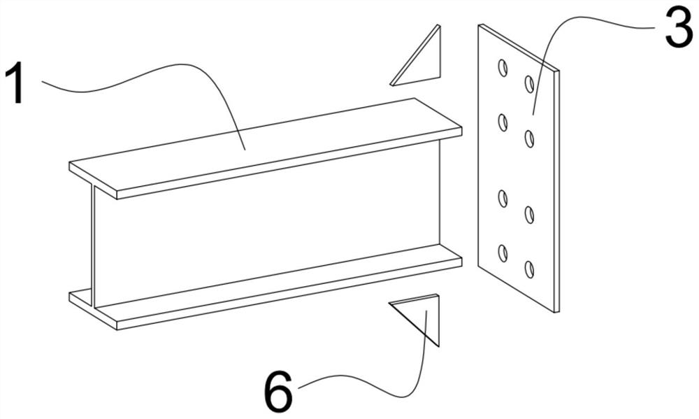
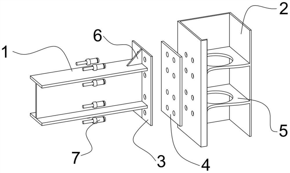
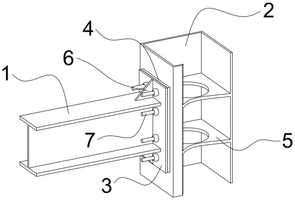
[0022] see Figure 1 to Figure 5 , a beam-column splicing joint, comprising a steel beam 1, a steel column 2, a steel beam end plate 3, a connecting plate 4 and a ring groove rivet 7; the steel beam end plate 3 is fixedly arranged at the end of the steel beam 1, and the steel beam end The plate 3 is set on one side of the steel column 2, and the connecting plate 4 is set between the steel beam end plate 3 and the steel column 2; the steel beam end plate 3, the connecting plate 4 and the side of the steel column are all provided with bolt holes, and the steel beam end The plate 3, the connecting plate 4 and the side of the steel column are fixedly connected by the ring groove rivet 7 arranged in the bolt hole.

[0023] The steel girder end plate 3 is welded to the steel girder, and stiffeners 6 are prefabricated and welded at right angles between the steel girder end plate 3 and...


PUM


Abstract

The invention discloses a beam column splicing joint. The beam column splicing joint comprises a steel beam, a steel column, a steel beam end plate, a connecting plate and ring groove rivets; the steel beam end plate is fixedly arranged at the end part of the steel beam, the steel beam end plate is arranged on one side surface of the steel column, and the connecting plate is arranged between the steel beam end plate and the steel column; and bolt holes are correspondingly formed in the side surfaces of the steel beam end plate, the connecting plate and the steel column, and the side surfaces of the steel beam end plate, the connecting plate and the steel column are fixedly connected through the ring groove rivets arranged in the bolt holes. According to the beam column splicing joint, thebolt holes are formed in the side surface of the steel column with a closed section, the steel column, the connecting plate and the steel beam are connected together through the ring groove rivets, the joint connection in this way is reliable, the force transmission path is clear, and the defects such as crack, air holes, slag inclusion, incomplete fusion and incomplete penetration in the weldingprocess are effectively avoided.

Description

technical field [0001] The invention relates to the technical field of building structures, in particular to a beam-column joint. Background technique [0002] The modular assembled multi-story steel structure is spliced ​​on-site by factory-processed modules, which has the advantages of rapid construction, reduced labor intensity, and reduced construction pollution. It is a green and environmentally friendly building and an innovative technology in the steel structure construction industry. [0003] Most of the beam-column splicing joints are bolt splicing plus on-site welding. Welding process There is always welding residual stress after welding. At the same time, due to the rapid cooling of the heat-affected zone of the welded parts, under the condition of high carbon content, it is easy to produce quenched martensite and cracks; the control is not in place during the welding process, Defects such as pores, slag inclusions, lack of fusion, and lack of penetration are pro...

Claims


Application Information

Patent Timeline
Patent Type & Authority Applications(China)
IPC IPC(8): E04B1/58E04B1/24
CPCE04B1/2403E04B1/5812E04B1/5831E04B2001/2406E04B2001/2454
Inventor 郝际平安炜佳郭亮
Owner XI'AN UNIVERSITY OF ARCHITECTURE AND TECHNOLOGY
Why Eureka
Try Eureka