Novel centrifugal granulated fertilizer dryer

A granular fertilizer and centrifugal technology, applied in non-progressive dryers, dryers, drying solid materials, etc., can solve the problems of fertilizers being easily broken into powder and poor drying effect

Inactive Publication Date: 2020-10-23
王永成
View PDF5 Cites 7 Cited by
  • Summary
  • Abstract
  • Description
  • Claims
  • Application Information

AI Technical Summary

Problems solved by technology

[0005] The purpose of the present invention is to provide a new type of centrifugal granular fertilizer dryer with good drying e

Method used


Image

  • Novel centrifugal granulated fertilizer dryer
  • Novel centrifugal granulated fertilizer dryer
  • Novel centrifugal granulated fertilizer dryer

Examples


Embodiment 1

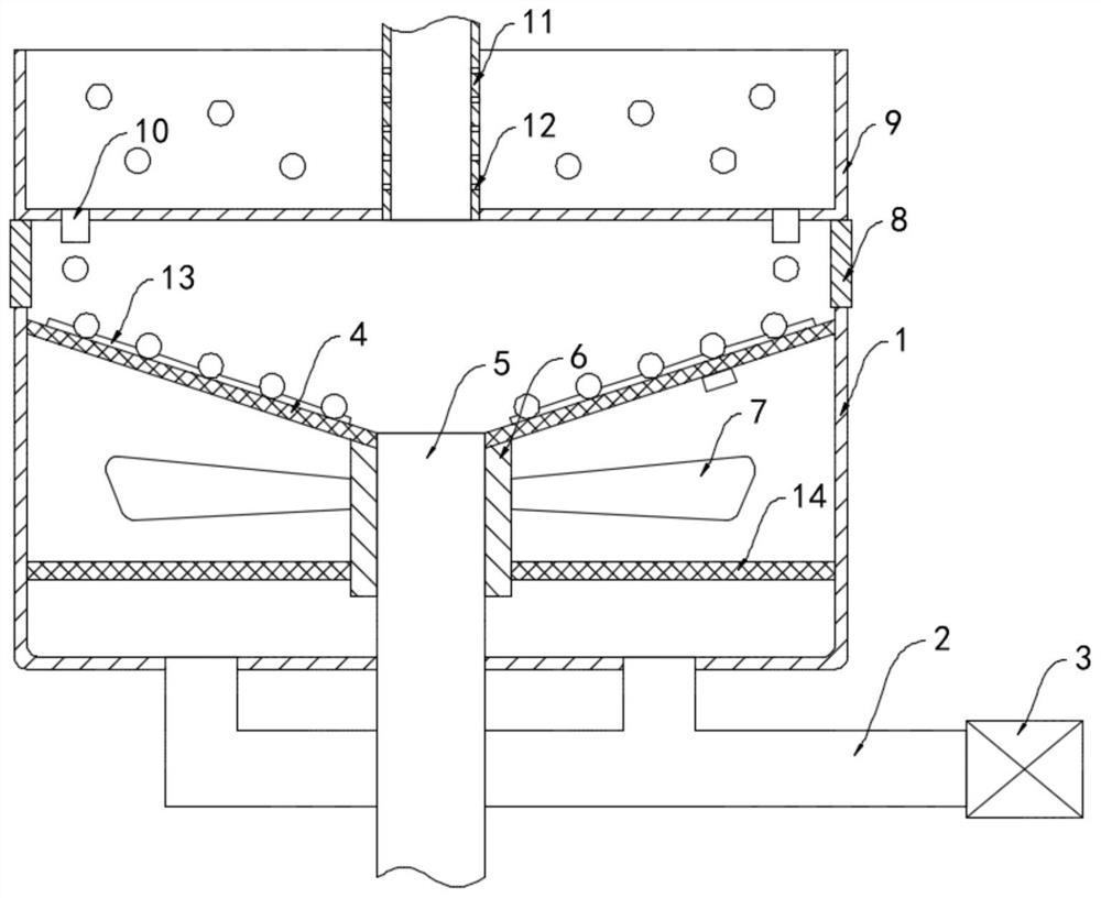
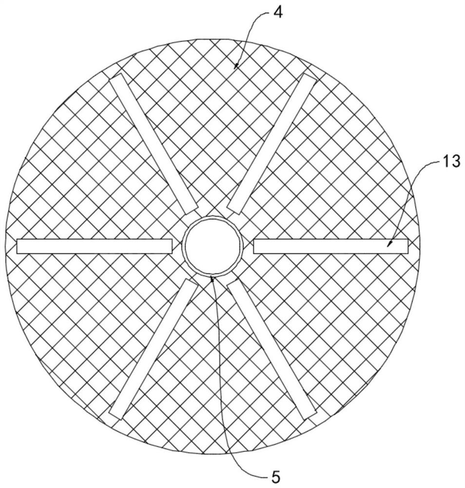
[0024] Such as Figure 1-2 As shown, a novel centrifugal granular fertilizer dryer includes a housing 1, the lower end of the housing 1 is fixedly connected with an air intake pipe 2, and the other end of the air intake pipe 2 is fixedly connected with a hot air blower 3, and the upper end of the housing 1 is opened. , the inner side wall of the upper end of the housing 1 is rotatably connected with a drying screen 4, the drying screen 4 is set in a downwardly concave conical shape, and the upper surface of the drying screen 4 is circumferentially arranged with a plurality of The shunt bar 13 that extends all around.

[0025] The center of the bottom surface of the drying net plate 4 is fixedly connected with a feeding pipe 5, the lower end of the feeding pipe 5 runs through the bottom surface of the housing 1 and extends to the outside of the housing 1, and the outer rotating sleeve of the feeding pipe 5 is connected with a sliding sleeve 6. The upper end of the sleeve 6 is ...

Embodiment 2

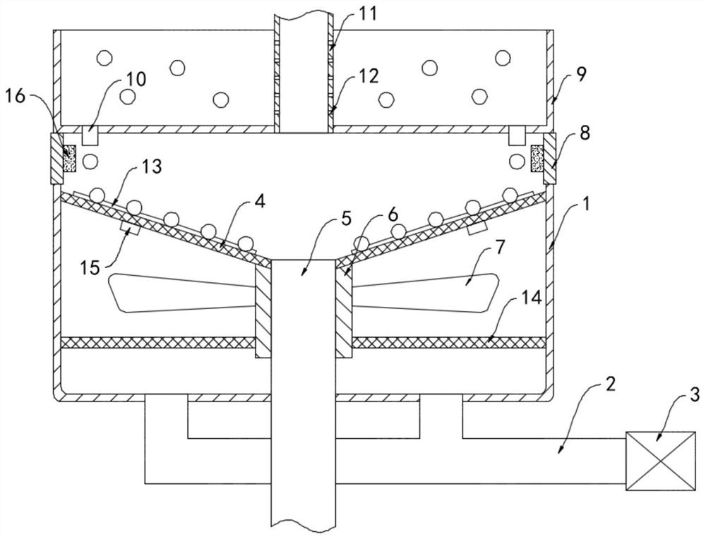
[0032] Such as Figure 3-4 As shown, the difference between this embodiment and Embodiment 1 is that two permanent magnet blocks 15 are installed on the bottom surface of the drying screen 4 , and a ring magnet 16 is fixedly installed on the inner wall of the enclosure 8 .

[0033] In this embodiment, the drying screen 4 drives the permanent magnet block 15 to rotate, and the two permanent magnet blocks 15 alternately approach and move away from the N pole and the S pole of the ring magnet 16. Under the magnetic force, the ring magnet 16 is opposite to the permanent magnet block 15 Periodically changing attractive and repulsive forces drive the drying screen 4 to repeatedly deform and shake, and then drive the spherical granular fertilizer on the drying screen 4 to repeatedly turn to make it fully contact with the hot air flow, further improving its drying effect.


PUM


Abstract

The invention belongs to the technical field of dryers, and particularly relates to a novel centrifugal granulated fertilizer dryer. The novel centrifugal granulated fertilizer dryer comprises a shell, wherein the lower end of the shell fixedly communicates with an air inlet pipe, the other end of the air inlet pipe fixedly communicates with an air heater, the upper end of the shell is open, the inner side wall of the upper end of the shell is rotationally connected with a drying net plate, the drying net plate is arranged in a downwards-concave conical face shape, the center of the bottom face of the drying net plate fixedly communicates with a conveying pipe, the lower end of the conveying pipe penetrates through the bottom face of the shell and extends out of the shell, the conveying pipe is in sleeve joint with a sliding sleeve in a rotating mode, and the upper end of the sliding sleeve is fixedly connected with the drying net plate. The novel centrifugal granulated fertilizer dryer can be flatly laid on the surface of the drying net plate according to different water contents and different centrifugal forces of spherical granulated fertilizers, the contact area between the spherical granulated fertilizers and hot air flow is large, the drying effect is good, the dried fertilizers can automatically fall off and be discharged from the conveying pipe, and sufficient and uniform drying is guaranteed.

Description

technical field [0001] The invention belongs to the technical field of dryers, in particular to a novel centrifugal granular fertilizer dryer. Background technique [0002] The current method of fertilizer production is basically high-tower granulation, so fertilizers are mostly spherical granules. During high-tower granulation, various raw materials need to be mixed to make slurry, sprayed down from the top of the high tower, and then cooled to become For spherical granular fertilizers, in order to facilitate the storage and transportation of fertilizers, the moisture inside the fertilizer particles needs to be removed by a dryer. [0003] Most of the traditional fertilizer dryers are drum dryers, which are repeatedly stirred by the lifting plate to make the granular fertilizer fully contact with the hot air to achieve the purpose of drying. However, the rotation direction of the drum dryer and the stirring method of the lifting plate Single, the lifting effect is poor, it...

Claims


Application Information

Patent Timeline
IPC IPC(8): F26B5/08F26B11/18F26B21/00F26B25/02
CPCF26B5/08F26B11/18F26B21/001F26B25/02
Inventor 王永成
Owner 王永成
Why Eureka
Try Eureka