Light interference detector

A detector and optical interference technology, used in instruments, measuring devices, scientific instruments, etc., can solve the problems that gas detectors are not widely used, the conversion accuracy of optoelectronic devices is high and low, and the cost of optoelectronic devices is high.

Pending Publication Date: 2020-10-23
陈迎春
View PDF12 Cites 0 Cited by
  • Summary
  • Abstract
  • Description
  • Claims
  • Application Information

AI Technical Summary

Problems solved by technology

[0004] Commonly used models of optical interference gas detectors are CJG10 and CJG100. For their structure and usage, please refer to the instruction manual of CJG10 optical interference methane detector (available on the Internet). For the optical path structure and measurement principle, please refer to patent documents: CN2091457U, CN2133889Y , CN102507498B, CJG10 optical interferometric methane detector has the disadvantages of inconvenient reading, needing naked eyes to interpret, and requiring manual calculation and recording data. Patent documents CN2091457U, CN2133889Y provide the use of photoelectric devices to receive optical signals and convert them into electrical signals, and automatically read The optical interferometric gas detector, as well as the method of taking pictures of the interference fringes and then analyzing the graphic images for reading, the photoelectric device receiving the light signal reading or the method of reading with the help of the camera, has a high degree of intelligence, convenient reading, and easy to output alarm signals, etc. However, the conversion accuracy of photoelectric devices varies, the cost of using photoelectric devices with high accuracy is high, the circuit design is complicated, and the image analysis method is also the same, resulting in the gas detectors of these methods not being widely used

Method used


Image

  • Light interference detector
  • Light interference detector

Examples


Embodiment Construction

[0022] The present invention will be further described below in conjunction with the accompanying drawings, so that those skilled in the art can understand the present invention.

[0023] All directional indications (such as up, down, left, right, front, back...) in the embodiments of the present invention are only used to explain the relative positional relationship between the various components in a certain posture (as shown in the drawings) , sports conditions, etc., if the specific posture changes, the directional indication also changes accordingly.

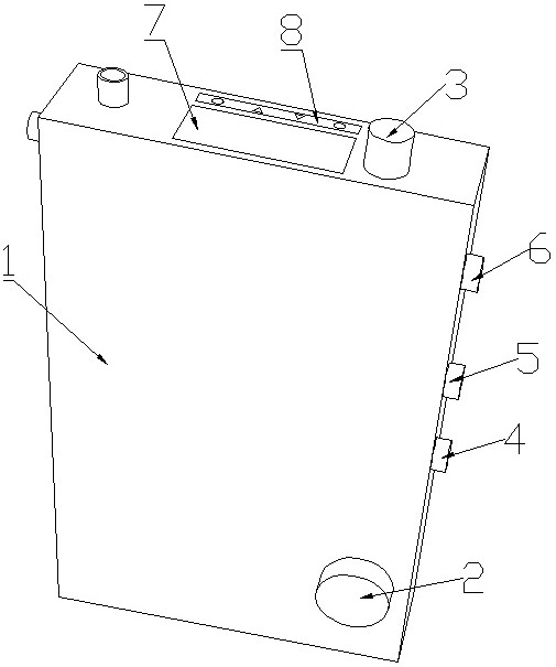
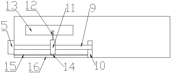
[0024] as attached figure 1 and 2As shown, it is an optical interference detector, which is a kind of optical interference gas detector, which can be improved on the basis of traditional gas detectors. Specifically, it includes a casing 1, and the casing 1 includes an optical interference detection gas detector. The optical interference detection gas path is used to introduce the gas to be detected, and a beam of light pa...


PUM


Abstract

The invention provides a light interference detector, which comprises a detection light path arranged in a housing. The detection light path comprises a light source, and light emitted by the light source is divided into two beams by the detection light path; the two beams of light respectively pass through a detection object and a standard object and then converge to generate interference; interference light is projected to a reticle; the reticle can be observed through an eyepiece; a pointer is arranged to point to the reticle; the pointer can be moved by a pointer regulator to point to different scales on the reticle; the pointer is fixedly connected with a sliding block; the sliding block contacts a sliding resistor; one end of the sliding resistor and the sliding block are respectively connected with one pole of a resistor reading circuit; and when the pointer and the light interference fringes are observed to coincide in position on the reticle through the eyepiece, the reading key is pressed down, the resistance reading circuit reads the resistance value between one end of the sliding resistor corresponding to the position of the pointer and the sliding block, the resistancevalue is converted into a measurement value of the detection object after being operated by a single-chip microcomputer, and the measurement value of the detection object is displayed outwards through a display screen.

Description

technical field [0001] The invention relates to the technical field of optical detection instruments, in particular to an optical interference detection instrument. Background technique [0002] A typical optical interference detector is an optical interference gas detector, which is widely used in the field of coal mine gas detection due to its advantages of accuracy, reliability and high precision. [0003] The principle of detecting gas concentration by light interference method is: when the light passes through the standard gas chamber and the detection gas chamber, due to the difference in the gas concentration filled in the standard gas chamber and the detection gas chamber, the refractive index of the light will change, forming a light The two beams of light with path difference converge to form interference fringes. The movement amount or width of the interference fringes is related to the refractive index. The refractive index corresponds to the concentration of the...

Claims


Application Information

Patent Timeline
IPC IPC(8): G01N21/45G01N21/01
CPCG01N21/45G01N21/01G01N2021/458
Inventor 陈迎春
Owner 陈迎春
Why Eureka
Try Eureka