
Memory alignment plugging method and system based on machine vision, equipment and storage medium

A machine vision, memory slot technology, applied in the field of image processing, can solve the problems of memory stick collision, high mounting density of motherboards, low labor efficiency, etc.

Inactive Publication Date: 2020-10-23
SUZHOU LANGCHAO INTELLIGENT TECH CO LTD
View PDF8 Cites 7 Cited by
  • Summary
  • Abstract
  • Description
  • Claims
  • Application Information

AI Technical Summary

Problems solved by technology

However, due to the high installation density of the motherboard, the large number of memory modules installed and generally fully configured operation, the efficiency of manual work is low, the insertion and removal operations are time-consuming and laborious, and the labor intensity of workers is high and easily injured.
Moreover, when a large number of memory sticks are inserted, it is easy to cause inaccurate alignment between the memory sticks and the memory slots due to external environmental influences during assembly, such as vibration, which will cause the memory sticks to collide with the memory sockets during insertion. On the groove wall of the groove, the gold finger of the memory stick is damaged or broken, and the memory slot is damaged

Method used


Image

  • Memory alignment plugging method and system based on machine vision, equipment and storage medium
  • Memory alignment plugging method and system based on machine vision, equipment and storage medium
  • Memory alignment plugging method and system based on machine vision, equipment and storage medium

Examples


Embodiment Construction

[0047] The following will clearly and completely describe the technical solutions in the embodiments of the present invention with reference to the accompanying drawings in the embodiments of the present invention. Obviously, the described embodiments are only some, not all, embodiments of the present invention. Based on the embodiments of the present invention, all other embodiments obtained by persons of ordinary skill in the art without making creative efforts belong to the protection scope of the present invention.

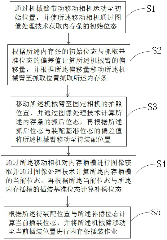
[0048] Please refer to figure 1 , figure 1 It is a schematic diagram of the overall structure of a specific embodiment provided by the present invention.

[0049] In a specific embodiment provided by the present invention, the machine vision-based memory alignment insertion method mainly includes five steps, which are:

[0050] S1. Drive the mobile camera to move to the initial position through the mechanical arm, and make the mobile camera obtain the initia...


PUM


Abstract

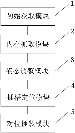
The invention discloses a memory alignment plugging method and system based on machine vision, equipment and a storage medium. The method comprises the steps of: driving a mobile camera to move to aninitial position through a mechanical arm, and obtaining the initial state of a memory bank; moving the mechanical arm to a grabbing position to grab the memory bank according to the deviation value of the initial state of the memory bank and a grabbing reference state; moving the mechanical arm to a photographing position of a fixed camera, calculating the post-grabbing state of the memory bank,and moving the mechanical arm to a position to be assembled according to the deviation value of the post-grabbing state of the memory bank and an assembling reference state; performing image acquisition on a memory slot, calculating the current state of the memory slot, and calculating a compensation state according to the current state of the memory slot and an insertion reference state of the memory slot; and calculating a current plugging mounting state according to the position to be assembled and the compensation state, and moving the mechanical arm to the current plugging mounting position to perform memory bank plugging mounting operation. According to the method, system, equipment and storage medium of the invention, the memory plugging mounting operation efficiency can be improved, accurate alignment of the memory bank and the memory slot is ensured, and collision accidents in the plugging mounting operation process are prevented.

Description

technical field [0001] The invention relates to the technical field of image processing, in particular to a machine vision-based memory alignment insertion method. The invention also relates to a machine vision-based memory aligning and plugging system, a device and a storage medium. Background technique [0002] With the development of electronic technology in China, more and more electronic devices have been widely used. [0003] A server is an important part of electronic equipment and a device that provides computing services. Since the server needs to respond to and process service requests, generally speaking, the server should have the ability to undertake and guarantee services. According to the different types of services provided by the server, it is divided into file server, database server, application server, WEB server, etc. [0004] In the era of big data, a large number of IT equipment will be centrally placed in the data center. These data centers contai...

Claims


Application Information

Patent Timeline
IPC IPC(8): G06T7/00G06T7/80
CPCG06T7/0004G06T7/80G06T2207/10004G06T2207/30108
Inventor 刘彬苑森康
Owner SUZHOU LANGCHAO INTELLIGENT TECH CO LTD
Learn More