Electron beam transient energy chirp reconstruction method

A transient energy, electron beam technology, applied in electrical components, electromagnetic transmitters, electromagnetic wave transmission systems, etc., can solve problems such as the inapplicability of RF lateral deflectors

Active Publication Date: 2020-10-23
SHANGHAI NORMAL UNIVERSITY
View PDF18 Cites 1 Cited by
  • Summary
  • Abstract
  • Description
  • Claims
  • Application Information

AI Technical Summary

Problems solved by technology

For low-energy ultra-short electron beams, RF transverse deflectors are not suitable due to the large change in the beam chirp distribution over short distances

Method used


Image

  • Electron beam transient energy chirp reconstruction method
  • Electron beam transient energy chirp reconstruction method
  • Electron beam transient energy chirp reconstruction method

Examples


Embodiment Construction

[0038] Below in conjunction with embodiment and accompanying drawing, the present invention will be further described

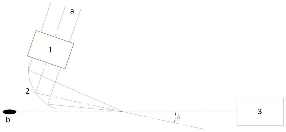
[0039] Diagnosis device for electron beam transient energy chirp reconstruction method of the present invention (as attached figure 1 shown). The chirped pulsed laser a interacts with the chirped electron beam b after being focused by the delayer 1 and the parabolic mirror 2, and the energy spectrum and lateral divergence angle distribution of the chirped electron beam b are diagnosed by the electronic energy spectrometer 3, and the modulation is carried out reconstruction method (as attached figure 2 shown), including the following steps:

[0040] A. Use FROG or SPIDER to measure the spectral phase and spectral intensity distribution of the chirped pulse laser a, and obtain the center frequency ω of the chirped pulse laser a 0 and chirp parameter b 0 ;

[0041] B. Establish a diagnostic optical path: the chirped pulse laser a is focused by the delayer...


PUM


Abstract

The invention discloses an electron beam transient energy chirp reconstruction method, and relates to the technical field of electron beam transient energy chirp diagnosis. The electron beam transientenergy chirp reconstruction method comprises steps that a tightly-focused chirped pulse laser a is focused by a delayer (1) and a parabolic mirror (2) and then interacts with a chirped electron beamb, energy spectrum and transverse divergence angle distribution of the chirped electron beam b are analyzed by an electron spectrometer (3), Fourier transform of an energy domain is applied to realizereconstruction of transient energy chirp of the electron beam, and the reconstruction method comprises the steps of A-E. Compared with the prior art, the method has the advantages that firstly, electron beam bunch transient energy chirp can be reconstructed; secondly, the devices are simple and convenient, the method can be realized only by common mature, stable and reliable devices such as the paraboloidal mirror and the electronic spectrometer; thirdly, the expansibility is good, the adopted pulse laser can be expanded to any waveband. The method is of great significance to control optimization of small accelerators and dynamic behavior exploration and optimization of electron beams in various novel accelerators.

Description

technical field [0001] The invention relates to the technical field of electron beam transient energy chirp diagnosis, in particular to a reconstruction method for electron beam transient energy chirp. Background technique [0002] In optics, the characteristic that signal frequency changes with time is called chirp. For particle beams, chirp is expressed as the energy of particle beam changes with time. Traditional femtosecond ultrashort electron beam energy chirp diagnosis methods mainly use radio frequency transverse deflectors, such as X-band. The main principle of X-band is that when the electron beam is transmitted in the radio frequency cavity, a high frequency radio frequency field is applied laterally on it. Energy chirp diagnostics of electron beams can be obtained with spectrometers. In 2014, the Stanford Linear Accelerator Center used a 1m-long X-band device to realize the energy chirp diagnosis of electron beams with energies of 4.7GeV and 15.2GeV and pulse wi...

Claims


Application Information

Patent Timeline
Patent Type & Authority Applications(China)
IPC IPC(8): H04B10/2513H04B10/54
CPCH04B10/25137H04B10/54
Inventor 张志钧周诗怡刘建胜余昌海秦志勇王健硕焦旭辉严春晖曹玉腾
Owner SHANGHAI NORMAL UNIVERSITY
Why Eureka
Try Eureka