High-precision mechatronics control equipment

A control equipment, high-precision technology, applied in the direction of electrical equipment construction parts, electrical components, chemical instruments and methods, etc., can solve the problem of affecting the service life of mechatronic control devices, dust entering the computer, and affecting mechatronic control devices Normal use and other issues

Inactive Publication Date: 2020-10-23
嘉兴技师学院
View PDF0 Cites 0 Cited by
  • Summary
  • Abstract
  • Description
  • Claims
  • Application Information

AI Technical Summary

Problems solved by technology

[0003] The existing mechatronics needs to be controlled by a computer, but the computer will emit a lot of heat during long-term use, and the electronic components in the computer will be damaged by the staff in a high-temperature environment, which will affect the normal use of the mechatronics control device. And affect the service life of the mechatronic control device, but the existing m

Method used


Image

  • High-precision mechatronics control equipment
  • High-precision mechatronics control equipment
  • High-precision mechatronics control equipment

Examples


Embodiment 1

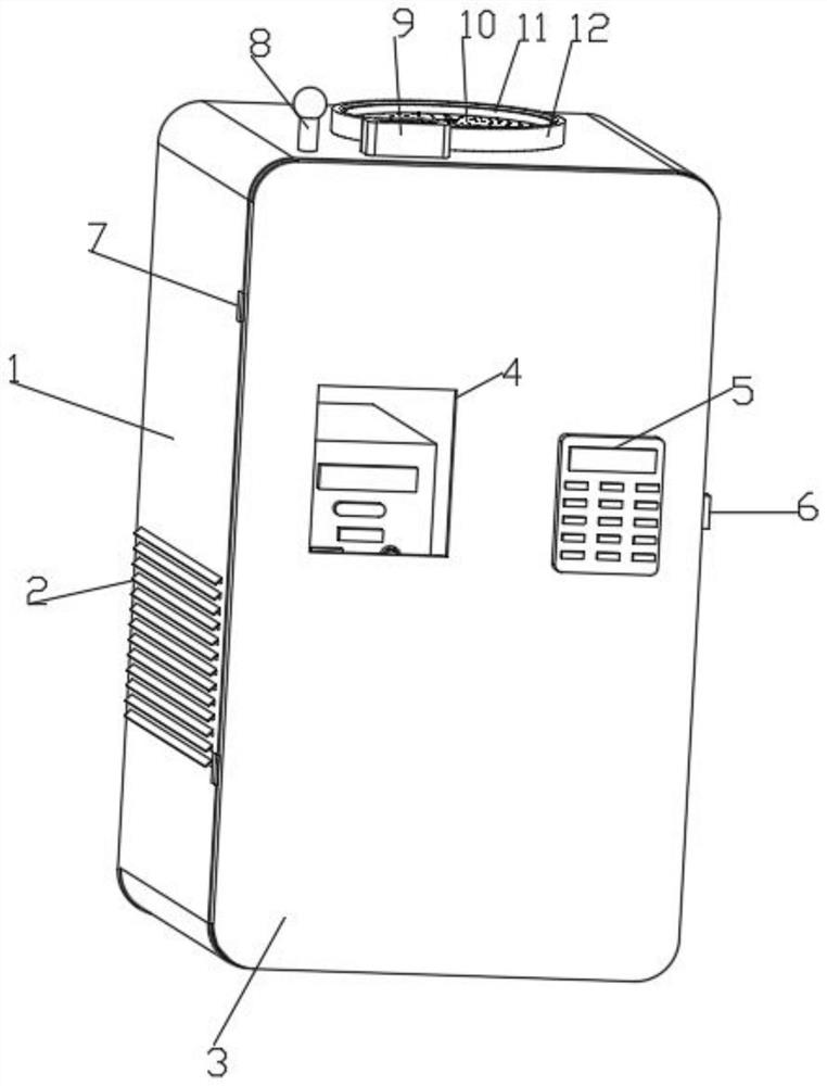
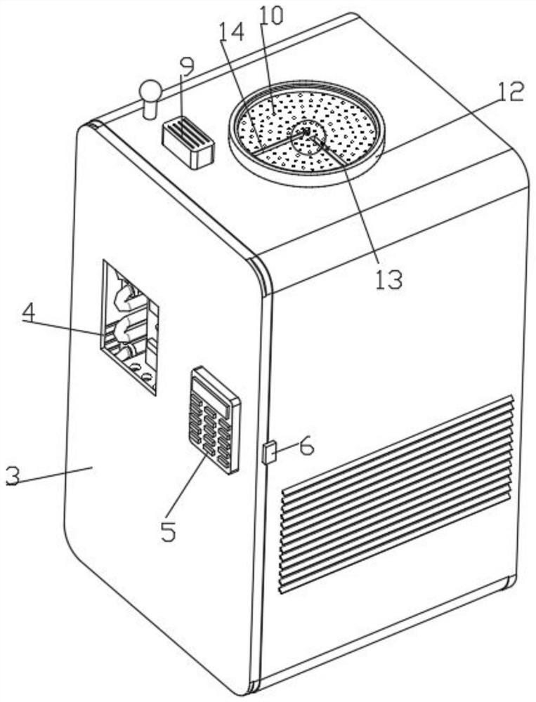
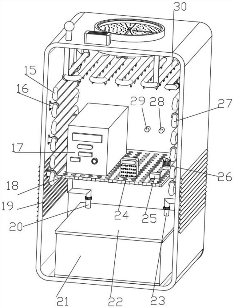
[0037] Such as Figure 1-8A high-precision electromechanical integrated control device is shown, including a box body 1, a first controller 5, an alarm lamp 8, a speaker 9, a control device 17, a second controller 24, an air switch 25, an automatic release button 26, a temperature Inductor 28, smoke sensor 29, driving motor 35 and water pump 36, the front side wall of box body 1 is connected with door panel 3, and the first controller 5 is fixedly installed on door panel 3, and the top of box body 1 is fixedly connected with alarm lamp 8, Loudspeaker 9 and air intake pipe 12, the middle end of air intake pipe 12 is fixedly connected with support ring 37, and support ring 37 is connected with straight barrel 11, and the bottom of straight barrel 11 is fixedly connected with filter plate 10 for filtering air dust, the bottom of air intake pipe 12 Be fixedly connected with support plate 34 by fixing bolt, support plate 34 top middle end places are fixedly installed with drive mot...

Embodiment 2

[0039] Embodiment 2 is a further improvement to Embodiment 1.

[0040] Such as Figure 1-8 A high-precision electromechanical integration control device shown includes a box body 1, a first controller 5, a warning light 8, a speaker 9, a control device 17, a second controller 24, an air switch 25, an automatic release button 26, A temperature sensor 28, a smoke sensor 29, a drive motor 35 and a water pump 36, the front side wall of the box body 1 is connected with a door panel 3, the left and right side walls of the box body 1 are respectively fixedly connected with a lock 6 and a hinge 7, the lock 6 and the The hinges 7 are all connected with the door panel 3, and the door panel 3 is provided with a glass window 4 for conveniently observing the internal situation of the box body 1. The first controller 5 is fixedly installed on the box body 1, and the top of the box body 1 is fixedly connected with an alarm lamp 8 and a loudspeaker. 9 and the air intake pipe 12, the middle e...

Embodiment 3

[0042] Embodiment 3 is a further improvement to Embodiment 1.

[0043] Such as Figure 1-8 A high-precision electromechanical integration control device shown includes a box body 1, a first controller 5, a warning light 8, a speaker 9, a control device 17, a second controller 24, an air switch 25, an automatic release button 26, A temperature sensor 28, a smoke sensor 29, a drive motor 35 and a water pump 36, a door panel 3 is connected to the front side wall of the box body 1, a first controller 5 is fixedly installed on the door panel 3, and an alarm light 8 is fixedly connected to the top of the box body 1 , loudspeaker 9 and air intake pipe 12, and the middle end of the air intake pipe 12 is fixedly connected with a support ring 37, and the support ring 37 is connected with a straight cylinder 11, and the bottom of the straight cylinder 11 is fixedly connected with a filter plate 10 for filtering air dust, and the air intake pipe 12 The bottom is fixedly connected with a ...


PUM


Abstract

The invention relates to high-precision mechatronics control equipment in the technical field of mechatronics. The equipment comprises a box body, the box body is provided with a door plate, the box body is also provided with an alarm lamp, a loudspeaker and an air inlet pipe, the air inlet pipe is provided with a support ring, the support cylinder is provided with a straight cylinder, the straight cylinder is provided with a filter plate, a support plate is arranged on the air inlet pipe, a driving motor is arranged on the support plate, and is provided with fan blades, a dust receiving frameis provided with a dust removing structure, an air outlet hole is formed in the box body, the box body is provided with a dust blocking inclined plate, a mounting frame is arranged on the box body, the mounting frame is provided with a top serpentine water pipe, a left serpentine water pipe and a right serpentine water pipe, the top serpentine water pipe, the left serpentine water pipe and the right serpentine water pipe are connected, the top serpentine water pipe is provided with a spray head, the spread head is provided with a first electromagnetic valve, the left serpentine water pipe isprovided with a second electromagnetic valve, and is further provided with a water inlet pipe, the water inlet pipe is provided with a water tank cover, the water tank cover is arranged at the top ofa water tank, the water tank is provided with a water pump, the water pump is provided with a water outlet pipe, and the water outlet pipe is connected with the right serpentine water pipe. The heat dissipation treatment of the control equipment is facilitated, and the control equipment is prevented from being damaged by too high temperature.

Description

technical field [0001] The invention relates to the technical field of mechatronics, in particular to a high-precision mechatronics control device. Background technique [0002] Mechatronics, also known as mechanical and electronic engineering, is a kind of mechanical engineering and automation. With the rapid development of mechatronics technology, the concept of mechatronics has been widely accepted and widely used by us. With the rapid development of computer technology and widespread Application, mechatronics technology has achieved unprecedented development, mechatronics technology is the organic combination of mechanical technology, electrical and electronic technology, microelectronics technology, information technology, sensor technology, interface technology, signal conversion technology and other technologies, and Comprehensively applied to the comprehensive technology in practice, modern automatic production equipment can almost be said to be mechatronic equipment...

Claims


Application Information

Patent Timeline
IPC IPC(8): H05K7/20B01D46/10B01D46/00A62C3/16
CPCH05K7/20209H05K7/20272H05K7/20281B01D46/10A62C3/16B01D46/681
Inventor 周斌斌
Owner 嘉兴技师学院
Why Eureka
Try Eureka