Supercharge Your Innovation With Domain-Expert AI Agents!

Electrolyte layer-anode composite member for fuel cell, cell structure, fuel cell, and method for manufacturing composite member

An electrolyte layer and fuel cell technology, applied in fuel cells, battery electrodes, solid electrolyte fuel cells, etc., can solve problems such as power generation performance degradation

Active Publication Date: 2020-10-23
SUMITOMO ELECTRIC IND LTD
View PDF9 Cites 0 Cited by
  • Summary
  • Abstract
  • Description
  • Claims
  • Application Information

AI Technical Summary

Problems solved by technology

Separation between the solid electrolyte layer and the anode causes a significant reduction in power generation performance

Method used


Image

  • Electrolyte layer-anode composite member for fuel cell, cell structure, fuel cell, and method for manufacturing composite member
  • Electrolyte layer-anode composite member for fuel cell, cell structure, fuel cell, and method for manufacturing composite member
  • Electrolyte layer-anode composite member for fuel cell, cell structure, fuel cell, and method for manufacturing composite member

Examples


manufacture example 1

[0157] Anode A was produced by the following steps.

[0158] As an anode material, a mixed powder containing a spinel-type composite oxide (NiFe) containing Ni and Fe synthesized by an impregnation method was prepared 2 O 3 , the average particle size P 0 : 10 μm, 80% by volume) and a binder (acrylic resin, 20% by volume). Using this mixed powder, uniaxial press molding was performed to obtain a circular sheet-like molded body (precursor of an anode) having a diameter of 140 mm and a thickness of 0.8 mm.

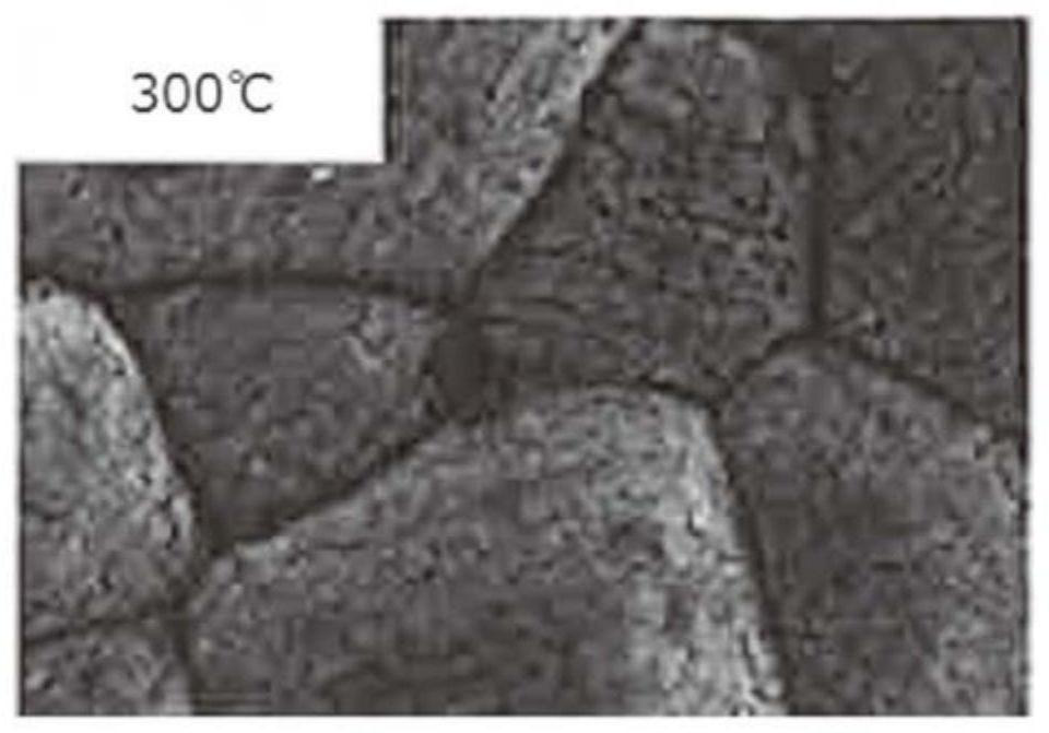
[0159] Then, in air, the obtained precursor of the anode was heated at 600°C for 1 hour to remove the binder, and thereafter fired at 1350°C for 2 hours in an oxygen atmosphere. Subsequently, the precursor of the anode was heated at 300° C. for 5 hours in a hydrogen atmosphere to reduce the composite oxide to a Ni—Fe composite metal, whereby Anode A was obtained. figure 2 A photograph of the surface of anode A taken using a scanning electron microscope (SEM) is shown. ...

manufacture example 2

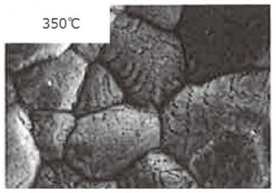
[0165]Anode B was produced and evaluated in the same manner as in Production Example 1, except that reduction treatment was performed at 350°C. Figure 8 The results are shown. in addition, image 3 A photograph of the surface of anode B taken using SEM is shown. The ratio of the bulk density Db of the anode B to the true density Dr of the Ni—Fe composite metal was 56%, and the particle diameter Pa of the particulate matter was 10 μm. In addition, the pore size P formed in the granular p is 130nm.

manufacture example 3

[0167] An anode C was produced and evaluated in the same manner as in Production Example 1, except that the reduction treatment was performed at 400°C. Figure 8 The results are shown. in addition, Figure 4 A photograph of the surface of anode C taken using SEM is shown. The ratio of the bulk density Db of the anode C to the true density Dr of the Ni—Fe composite metal was 54%, and the particle diameter Pa of the particulate matter was 24 μm. In addition, the pore size P formed in the granular p is 105nm.


PUM

PropertyMeasurementUnit
diameteraaaaaaaaaa
densityaaaaaaaaaa
particle diameteraaaaaaaaaa

Abstract

Provided is an electrolyte layer-anode composite member for a fuel cell, the composite member comprises an anode and a solid electrolyte layer that has ion conductivity, and the anode is an aggregateof granular material that includes a composite metal. The composite metal contains elemental nickel and elemental iron, the granular material comprises a plurality of pores, the composite metal accounting for 80% by mass or more of the anode, and the bulk density of the anode is 75% or less of the true density of the composite metal. Also provided are a cell structure comprising the electrolyte layer-anode composite member for the fuel cell, and a cathode disposed on the solid-electrolyte-layer side.

Description

technical field [0001] The present disclosure relates to an electrolyte layer-anode composite part for a fuel cell, a battery structure, a fuel cell, and a method for manufacturing the composite part. This application claims priority from Japanese Patent Application No. 2018-039520 filed on March 6, 2018. The entire contents described in this Japanese Patent Application are incorporated herein by reference. Background technique [0002] An anode for a fuel cell (SOFC) generally contains a nickel (Ni) component as a catalyst. Such anodes are typically formed by sintering a granular material comprising nickel oxide (NiO). A composite part made of a solid electrolyte layer and an anode (electrolyte layer-anode composite part) is produced, for example, by forming an anode using a material containing NiO pellets, coating a solid electrolyte on its surface, and co-sintering. In addition, reduction treatment for reducing NiO to Ni is performed. This enhances the function of Ni ...

Claims


Application Information

Patent Timeline
Patent Type & Authority Applications(China)
IPC IPC(8): H01M4/90H01M4/86H01M4/88H01M8/124H01M8/12
CPCY02P70/50Y02E60/50H01M2300/0074H01M2004/8684H01M4/8621H01M4/8647H01M4/881H01M4/8889H01M4/8835H01M4/905H01M2008/1293H01M8/1246H01M8/1231H01M8/1213H01M4/8626H01M4/8652H01M4/9041H01M8/0258
Inventor 平岩千寻真岛正利东野孝浩水原奈保俵山博匡
Owner SUMITOMO ELECTRIC IND LTD
Features
  • R&D
  • Intellectual Property
  • Life Sciences
  • Materials
  • Tech Scout
  • Unparalleled Data Quality
  • Higher Quality Content
  • 60% Fewer Hallucinations
Learn More