
Dividing wall type continuous extraction tower

A technology of extraction tower and extraction unit, applied in the field of dividing wall continuous extraction tower

Pending Publication Date: 2020-10-27
李爱民
View PDF0 Cites 0 Cited by
  • Summary
  • Abstract
  • Description
  • Claims
  • Application Information

AI Technical Summary

Problems solved by technology

[0005] Through the above analysis, it is not difficult to find that the existing extraction tower, whether it is a packed extraction tower or a rotating disk extraction tower, is limited by the two-phase mixing effect and phase separation effect, and there is a large room for improvement in the separation efficiency of the tower , to attract a large number of engineering enthusiasts to continue to study, to develop a more efficient new extraction tower, and to continuously improve the technical level of the extraction device

Method used


Image

  • Dividing wall type continuous extraction tower
  • Dividing wall type continuous extraction tower
  • Dividing wall type continuous extraction tower

Examples


Embodiment

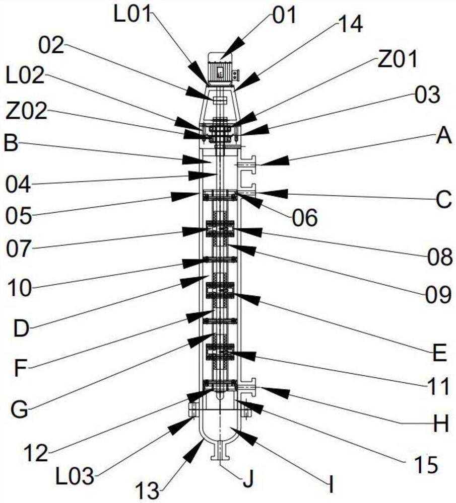
[0042] In order to make the present invention more comprehensible, an embodiment comprising 3 extraction units is described in detail below with reference to the accompanying drawings. The extraction units are upper, middle and lower extraction units from top to bottom.

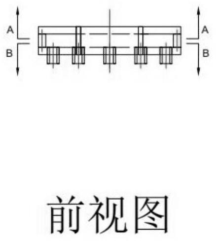
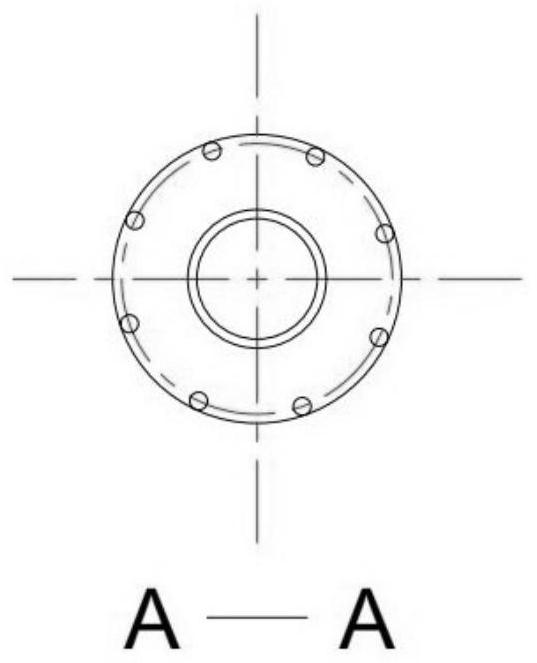
[0043] The present invention is a kind of dividing wall type continuous extraction tower, such as figure 1 As shown, it includes a motor 01, a frame 14, a shaft coupling 02, an upper end cover 03, a tower main shaft 04, a tower cylinder body 05, an upper feed distributor 06, an agitator 07, a screen cylinder 08, a partition body 09, a separator Phase plate 10, pin 11, lower feed distributor 12, lower end cover 13. The motor 01 is connected to the frame 14 through the screw 1 L01, and the frame 14 is connected to the upper end cover 03 through the screw 2 L02. The motor shaft is connected to the tower main shaft 04 in a threaded manner through the coupling 02, and the tower main shaft 04 passes through the upp...


PUM


Abstract

The invention relates to a dividing wall type continuous extraction tower, and belongs to the technical field of chemical equipment. The dividing wall type continuous extraction tower comprises a motor, a tower main shaft, a tower barrel body, an upper feeding distributor, a lower feeding distributor, a stirrer, an extraction unit, a light phase inlet, a heavy phase inlet, a light phase outlet anda heavy phase outlet; a motor is arranged at the upper end of the tower barrel, a tower main shaft is arranged along the central axis of the tower barrel, and the motor is connected with the tower main shaft; an up-and-down feeding distributor is arranged in the tower barrel body; a plurality of extraction units are continuously arranged between the upper feeding distributor and the lower feedingdistributor; a stirrer is arranged in the extraction unit; the upper feeding distributor is connected with the heavy phase inlet, and the lower feeding distributor is connected with the light phase inlet; and a light phase outlet is formed above the upper feeding distributor, and a heavy phase outlet is formed below the lower feeding distributor. According to the invention, in a plurality of continuously arranged extraction units, the physically separated mixing mass transfer area and clarification phase separation area are arranged to improve the mass transfer effect and the phase separationeffect and reduce the influence of back mixing; and the overall extraction effect is remarkably improved.

Description

technical field [0001] The invention relates to a partition-type continuous extraction tower, which belongs to the technical field of chemical equipment. In the present invention, the liquid flow direction of the extraction tower is defined as up and down directions, the light phase liquid flows from bottom to top, and the heavy phase liquid flows from top to bottom. Background technique [0002] In the late 1940s, due to the demand for nuclear fuel production, the technology of liquid-liquid extraction using two liquids with different densities that are immiscible has achieved considerable development, and has gradually become popular in petrochemical, chemical engineering, metallurgy, Food, traditional Chinese medicine extraction and atomic energy industry have been widely used. [0003] There are many types of extractors that extraction technology relies on, and extraction towers are one of them. As we all know, the extraction towers commonly used in the industry are ma...

Claims


Application Information

Patent Timeline
IPC IPC(8): B01D11/04
CPCB01D11/04B01D11/0426
Inventor 李爱民
Owner 李爱民
Learn More