Centrifugal vortex electrostatic dust collector

An electrostatic precipitator, centrifugal technology, applied in the field of centrifugal vortex electrostatic precipitator, can solve the problem of poor dust removal effect

Inactive Publication Date: 2020-10-27
释果阳
View PDF0 Cites 0 Cited by
  • Summary
  • Abstract
  • Description
  • Claims
  • Application Information

AI Technical Summary

Problems solved by technology

[0005] The purpose of the present invention is to provide a centrifugal vortex electrostatic precipitator with a long duration and excellent cleaning effect in view of the problem that the existing dust collector has poor dust removal effect.

Method used


Image

  • Centrifugal vortex electrostatic dust collector
  • Centrifugal vortex electrostatic dust collector
  • Centrifugal vortex electrostatic dust collector

Examples


Embodiment 1

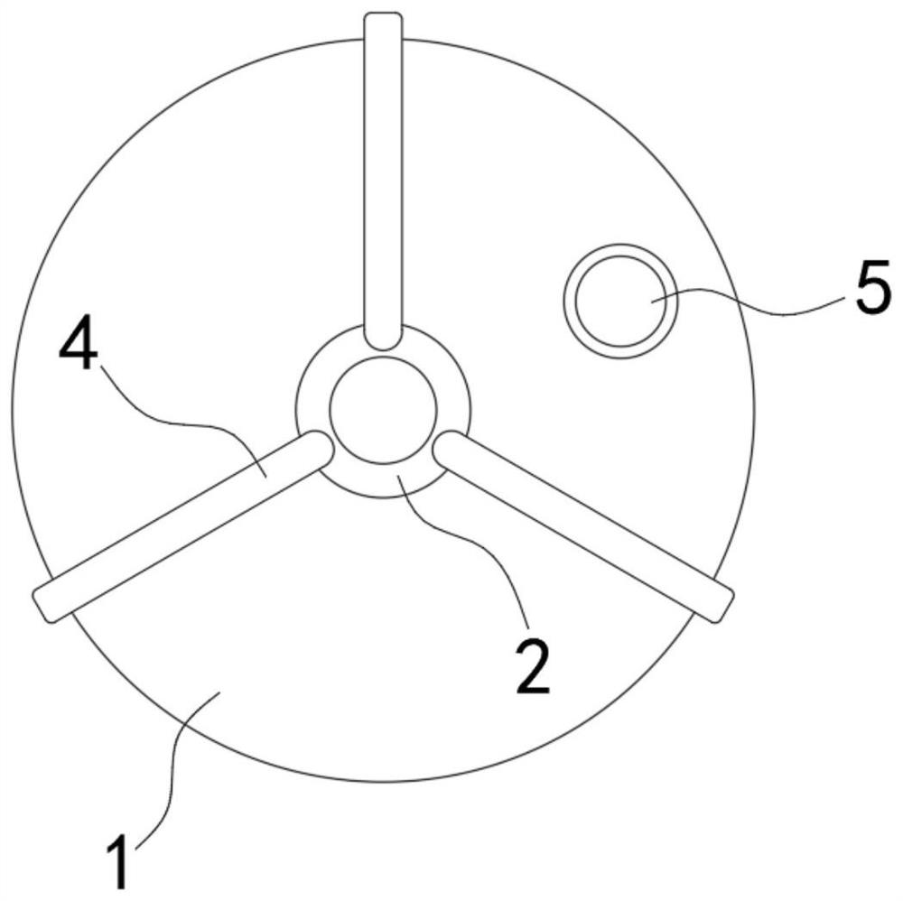
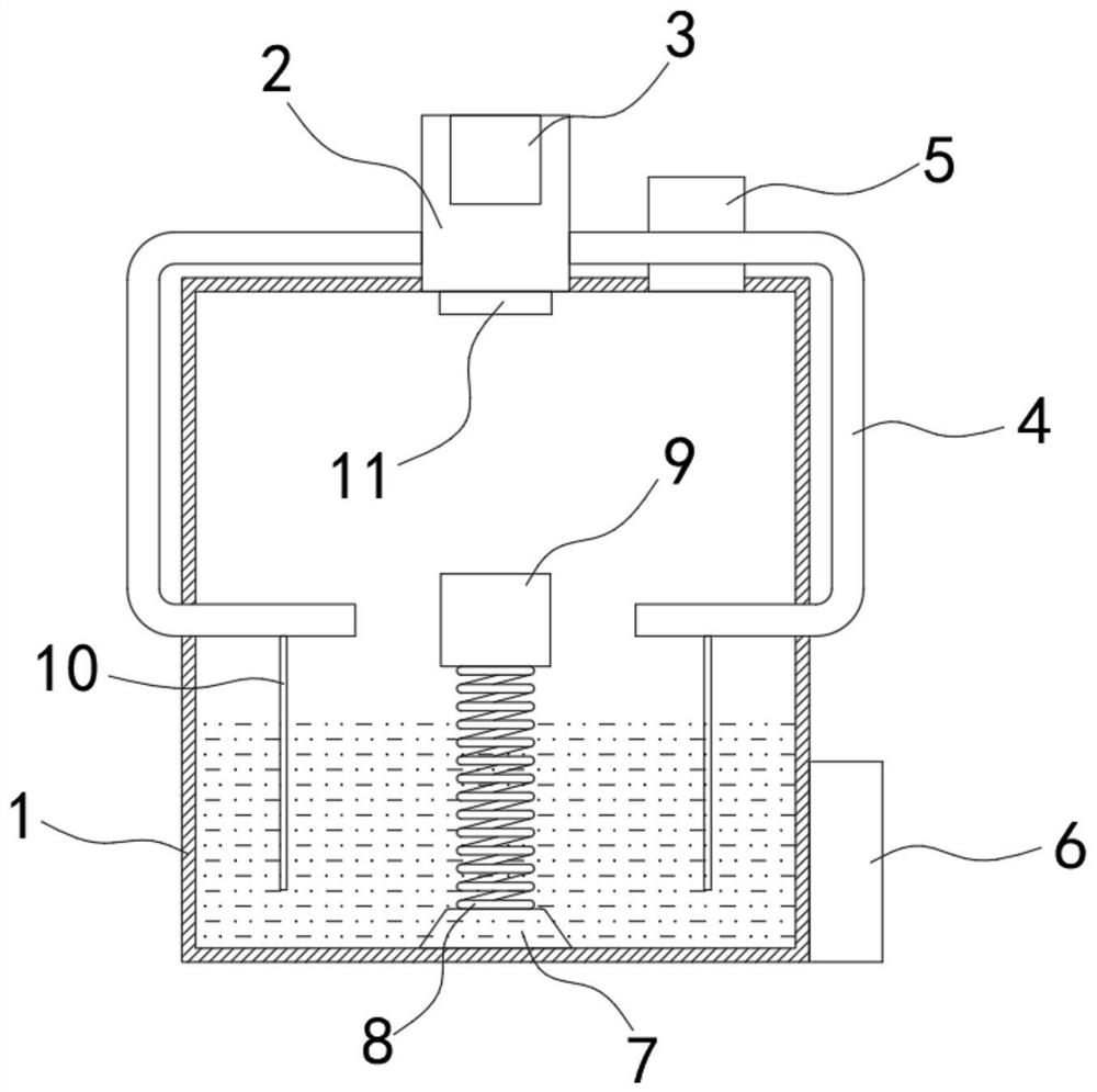
[0023] Such as Figure 1-3 As shown, a centrifugal vortex electrostatic precipitator includes a cylindrical, vertically arranged housing 1, in which water for dust removal is filled, and an air intake pipe 2 is fixedly connected to the upper end of the housing 1, and The air pipe 2 is fixedly connected with a conductive sheet 3, and the side wall of the air intake pipe 2 is fixedly connected with a plurality of shunt pipes 4. The size of each shunt pipe 4 is the same, and is evenly distributed around the air intake pipe 2, so that each shunt pipe 4 The air flow is balanced, the lower end of the shunt pipe 4 extends to the inside of the housing 1, the upper end of the housing 1 is provided with an exhaust pipe 5, the side wall of the housing 1 is fixedly connected with an electrostatic generator 6, and the bottom of the housing 1 The center position is fixedly connected with a mounting seat 7, and the upper end of the mounting seat 7 is fixedly connected with an eccentric sprin...

Embodiment 2

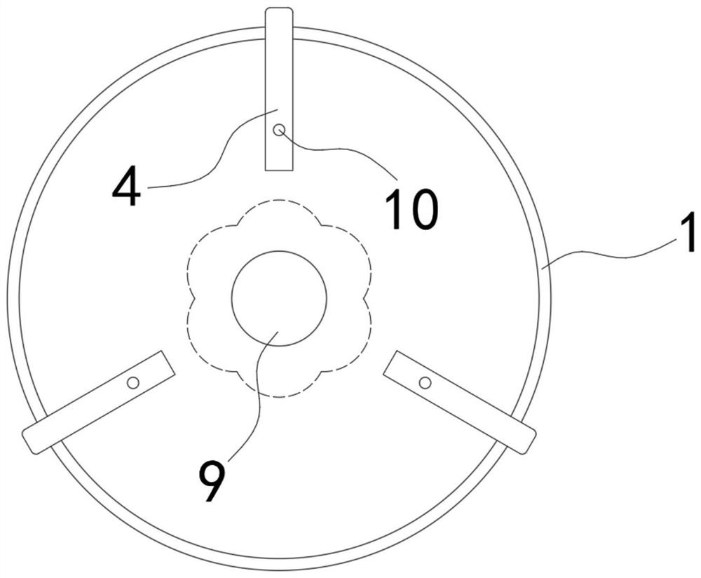
[0028] Such as Figure 4-5 As shown, the difference between this embodiment and Embodiment 1 is that the output ends of each shunt tube 4 are arranged sequentially along the tangential direction of the sputtering block 9, and the output ends of each shunt tube 4 are of different lengths, as shown in Figure 5 As shown, the output end of the shunt tube 4 is located below the liquid level.

[0029] In this embodiment, since each shunt pipe 4 is distributed in the same direction around the tangential direction of the sputtering block 9, and the output ends of each shunt pipe 4 are of different lengths, that is, the exhaust speed is different, so multiple pipes will be formed in the water. The water streams that rotate around the same center and have different flow velocities will form a vortex centered on the sputtering block 9 under the action of multiple streams, with the entrance at the top and the exit at the bottom, which can continuously sputter The large particle impuriti...


PUM


Abstract

The invention belongs to the field of dust collectors, and especially relates to a centrifugal vortex electrostatic dust collector. The dust collector comprises a cylindrical shell which is verticallyarranged. Water is contained in the shell, the upper end of the shell is fixedly connected with an air inlet pipe. A conducting strip is fixedly connected in the air inlet pipe. The side wall of theair inlet pipe is fixedly connected with a plurality of shunt pipes. The lower end of the shunt pipe extends into the shell. An exhaust pipe is arranged at the upper end of the shell. The side wall ofthe shell is fixedly connected with an electrostatic generator. A mounting base is fixedly connected to the center of the bottom of the shell, an eccentric spring is fixedly connected to the upper end of the mounting base, a cylindrical sputtering block is fixedly connected to the upper end of the eccentric spring, the output ends of the flow dividing pipes correspond to the sputtering block, andthe sputtering block is electrically connected with the mounting base through the eccentric spring. By arranging the sputtering block and a plurality of flow dividing pipes, airflow can impact the sputtering block from multiple directions, dust is fully diffused, the contact area with water is increased, and the dust collecting effect is improved.

Description

technical field [0001] The invention belongs to the field of dust collectors, in particular to a centrifugal vortex electrostatic dust collector. Background technique [0002] With the development of industrialization, the air quality in cities will be greatly affected, and smog is prone to occur, which affects the lives of residents. At present, dust in the air is generally purified by dust collectors. [0003] Dust collectors include dry dust collectors and wet dust collectors. The dry dust collector uses static electricity to attract and capture dust. However, the dust adheres to the electrostatic plate for a long time, and the electrostatic plate needs to be cleaned regularly, otherwise the dust removal effect will be reduced. It will be greatly reduced, and the wet dust collector generally passes the dust-containing gas directly into the water to make the dust and water contact and fuse, so as to play the role of dust removal, but in the actual use process, the diameter...

Claims


Application Information

Patent Timeline
Patent Type & Authority Applications(China)
IPC IPC(8): B03C3/011B03C3/017B03C3/40B03C3/34
CPCB03C3/011B03C3/017B03C3/34B03C3/40
Inventor 释果阳
Owner 释果阳
Why Eureka
Try Eureka