
General caliper automatic calibrating device

A verification device and caliper technology, applied in the direction of using mechanical devices, optical devices, measuring devices, etc., can solve the problems of disconnection between measurement and production, inability to provide timely and accurate feedback, and low verification efficiency, so as to improve verification efficiency and automation. , Eliminate the influence of subjective factors and reduce the effect of verification uncertainty

Inactive Publication Date: 2020-10-27
SHENYANG AIRCRAFT CORP
View PDF0 Cites 0 Cited by
  • Summary
  • Abstract
  • Description
  • Claims
  • Application Information

AI Technical Summary

Problems solved by technology

[0003] At present, the verification of general-purpose calipers is mainly done manually, but the traditional manual visual verification not only has a large workload, requires high technical experience for the verification personnel, but also has low verification efficiency.
The verification process is greatly affected by human subjective factors, resulting in low verification accuracy and poor reliability
At the same time, the verification data are all manually recorded and processed, lack of digital management means, and the data utilization rate is low
The verification period is fixed, and the verification results can only reflect the qualification of the caliper afterwards, which leads to the disconnection between measurement and production, and cannot provide timely and accurate feedback on the status of the calipers being used at the processing site, and the effectiveness of the verification work is poor.

Method used


Image

  • General caliper automatic calibrating device
  • General caliper automatic calibrating device
  • General caliper automatic calibrating device

Examples


Embodiment Construction

[0029] The present invention will be described in further detail below in conjunction with the accompanying drawings and specific embodiments.

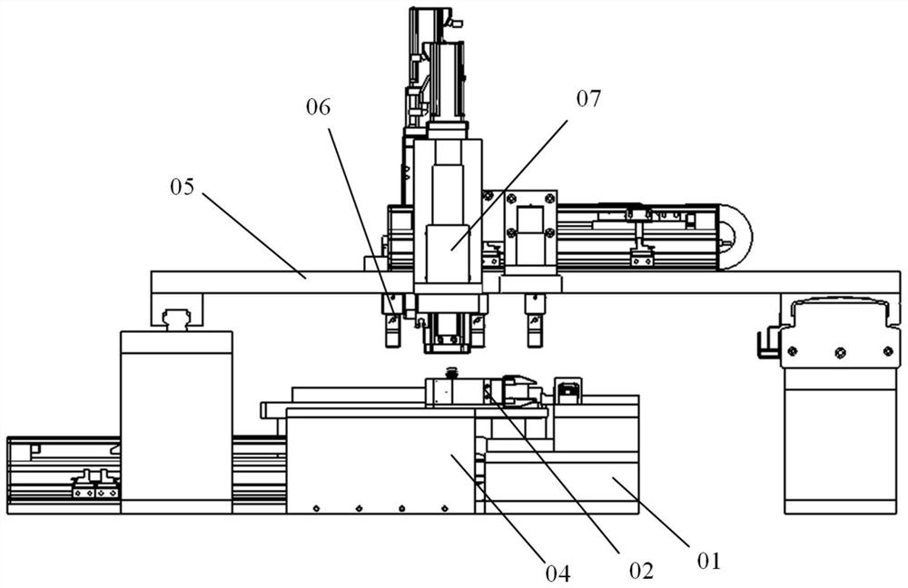
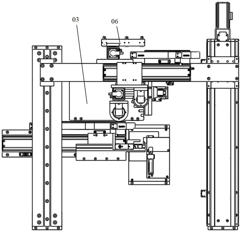
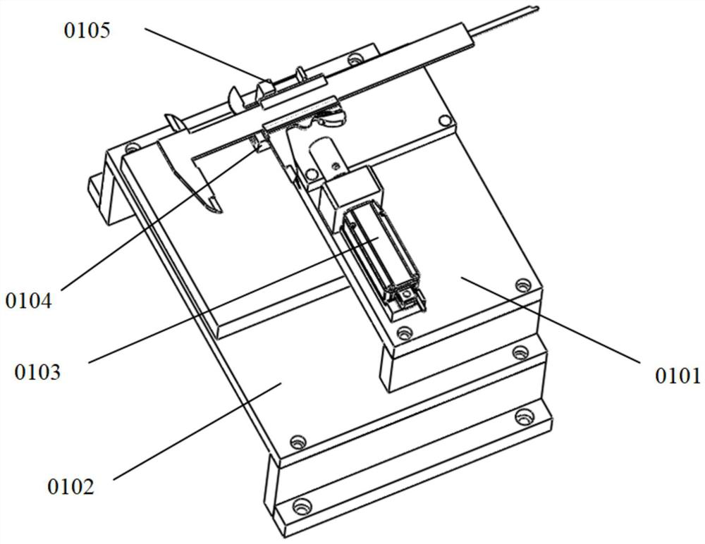
[0030] Such as figure 1 and figure 2 As shown, the caliper clamping and positioning mechanism 01 is installed at the near end of the console, the caliper clamping and dragging mechanism 02 is installed on the left side of the caliper clamping and positioning mechanism 01, the gauge block tray 03 is located at the far end of the console, and the edge of the tray is in line with the The left positioning block 0104 of the caliper clamping and positioning mechanism 01 is aligned to ensure the consistency of the lateral position when the gauge block is grasped.

[0031] The verification personnel first manually clamp the caliper to be tested on the clamping and positioning mechanism 01, and then select the caliper type in the verification software system and start the verification operation.

[0032] The first step is the verification o...


PUM


Abstract

The invention relates to a general caliper automatic calibrating device and belongs to the field of metering test. The device comprises a caliper clamping and positioning mechanism, a caliper clampingand dragging mechanism, a gauge block tray, a gauge block sliding groove, a double-guide-rail gantry type movement mechanism, a gauge block grabbing mechanism and a machine vision system. The measuring force of a clamping gauge block is controlled through a feedback voltage of a linear motor, the influence of subjective factors of manual operation is eliminated, control precision of the measuringforce is improved, and calibration uncertainty caused by the factors of the measuring force is reduced; two machine vision detection modules with different magnification ratios are adopted, automaticcomprehensive detection of multiple parameters such as the marking width, the indication error, the zero value error and the parallelism of a measuring jaw in a knife edge of the universal caliper isachieved at the same time, and detection efficiency and the automation degree of the universal caliper are improved. Through data analysis of the verification result, a general caliper risk early warning and quality control system can be established, full-life-cycle digital management of the caliper is realized, and the verification data utilization rate and the verification work effectiveness are improved.

Description

technical field [0001] The invention relates to the field of metrology and testing, and more specifically relates to an automatic verification device for a universal caliper. Background technique [0002] Universal calipers are easy to operate and have high precision, and are widely used in the machinery industry. Since the measurement of the universal caliper itself does not conform to the Abbe principle, the machining error and assembly error of the parts during the manufacture of the caliper, as well as the wear or even damage of the measuring surface during the use of the caliper, will cause the measurement error of the universal caliper and directly affect the machine. Product detection accuracy. Therefore, it is necessary to calibrate the universal caliper before and during use to ensure the measurement accuracy of the caliper. [0003] At present, the verification of universal calipers is mainly done manually, but the traditional manual visual verification not only ...

Claims


Application Information

Patent Timeline
Patent Type & Authority Applications(China)
IPC IPC(8): G01B5/00G01B11/00G01B11/02G01B11/26
CPCG01B5/00G01B11/00G01B11/02G01B11/26G01B21/042
Inventor 刘中阳李博文余厚云王梦斐
Owner SHENYANG AIRCRAFT CORP
Learn More