Optical lens with laser-induced periodic surface microstructure

A technology of optical lenses and microstructures, applied in optics, optical components, laser welding equipment, etc., can solve problems such as cumbersome processes, unstable optical functions, and uneven distribution of micro-nano structures

Inactive Publication Date: 2020-10-27
SUN YANG OPTICS DEV CO LTD
View PDF9 Cites 0 Cited by
  • Summary
  • Abstract
  • Description
  • Claims
  • Application Information

AI Technical Summary

Problems solved by technology

The problems of this method include: 1. It is not easy to uniformly coat the photoresist on the curved surface; 2. It is necessary to make a photomask, and it is difficult to perform precise lithography on the curved surface; 3. It is difficult to control the uniformity when etching on the curved surface
Although this method has the opportunity to be implemented on curved surfaces, the greater the curvature of the lens, the greater the difference in etching characteristics from the apex to the edge. At the same time, the arrangement of micro-nano structures is random and the sizes are inconsistent, resulting in uneven distribution of micro-nano structures on the lens. dysfunctional
In summary, although the lithographic etching method can fabricate micro-nano structures on flat substrates, the process is cumbersome and it is extremely difficult to implement on curved surfaces.

Method used


Image

  • Optical lens with laser-induced periodic surface microstructure
  • Optical lens with laser-induced periodic surface microstructure
  • Optical lens with laser-induced periodic surface microstructure

Examples


Embodiment Construction

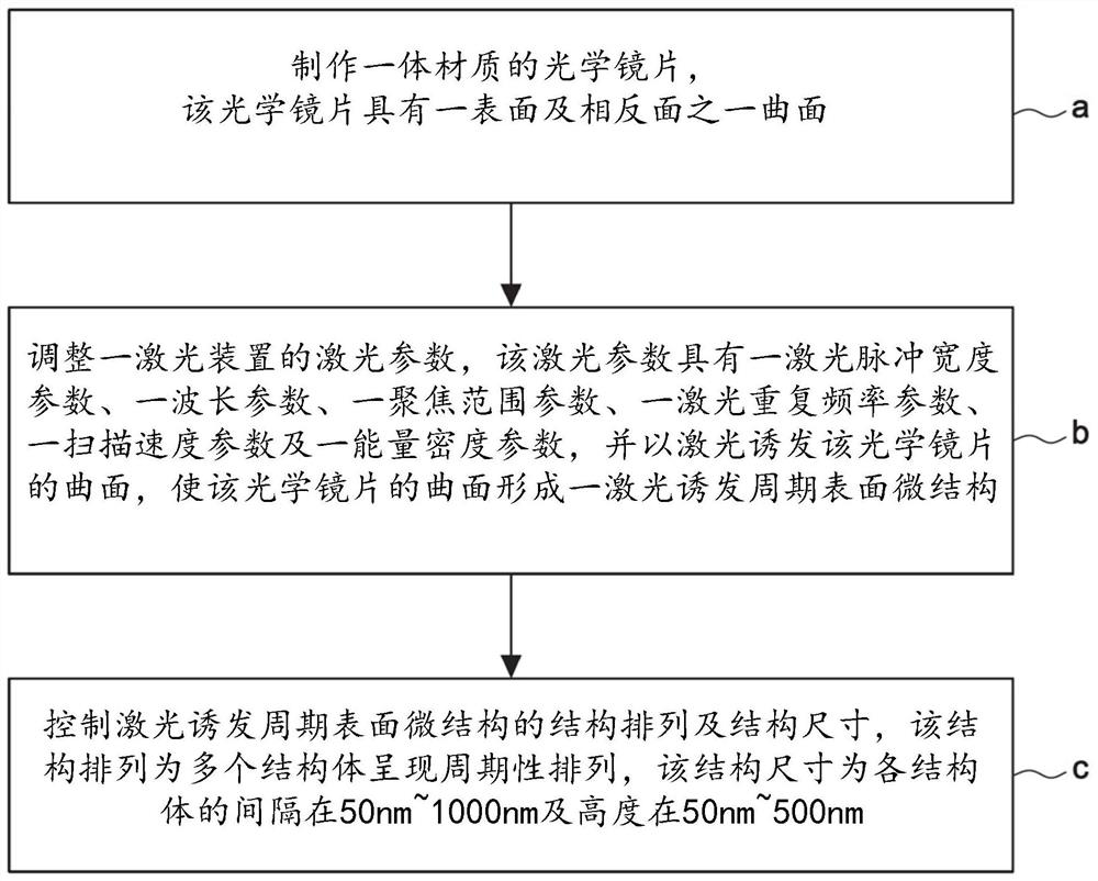
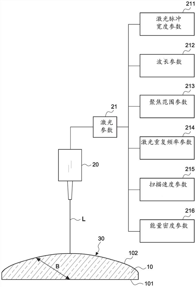
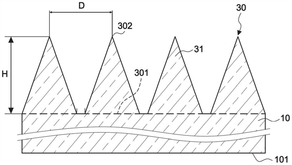
[0034] First, see figure 1 As shown in the flow chart, an optical lens with a laser-induced periodic surface microstructure of the present invention comprises the following steps: a). Making an optical lens 10 made of an integral material, the optical lens 10 has a surface 101 and an opposite surface A curved surface 102; b). Adjust the laser parameter 21 of a laser device 20, the laser parameter 21 has a laser pulse width parameter 211, a wavelength parameter 212, a focal range parameter 213, a laser repetition rate parameter 214, and a scanning speed parameter 215 and an energy density parameter 216, and induce the curved surface 102 of the optical lens 10 with a laser, so that the curved surface 102 of the optical lens forms a laser-induced periodic surface microstructure (Laser Induced Periodic Surface Structure, LIPSS) 30; and c) . Controlling the structure arrangement and structure size of the laser-induced periodic surface microstructure 30, the structure arrangement is...


PUM

PropertyMeasurementUnit
thicknessaaaaaaaaaa

Abstract

An optical lens with a laser-induced periodic surface microstructure includes an optical lens which is an integrated material and is provided with a surface and a curved surface opposite to the surface. The curved surface of the optical lens is induced by laser so that the curved surface of the optical lens forms a laser-induced periodic surface microstructure. The structural arrangement and the structural size of the laser-induced periodic surface microstructure are as follows: the structural arrangement is that a plurality of structural bodies are periodically arranged, and the structural size is that the structural bodies are separated at intervals of 50nm-1000nm and the height of each structural body is 50nm-500nm.

Description

technical field [0001] The invention relates to an optical lens with a laser-induced periodic surface microstructure, especially a microstructure with approximately periodicity on the curved surface of the optical lens, which makes the optical lens hydrophobic or hydrophilic, or reduces light The reflectance of the curved surface incident on the optical lens, etc., this microstructure is produced by using ultrafast laser light to irradiate the curved surface of the optical lens, or the thin film of the curved surface of the optical lens. Background technique [0002] Form an attachment material on the surface of the optical lens, and then fabricate the micro-nano structure on the attachment material. Usually, the attachment material is a material that is easy to process such as photosensitivity, polymer, or low hardness. It is different from the material of the optical lens to be attached. The practical problem is that there is a difference in the refractive index between th...

Claims


Application Information

Patent Timeline
Patent Type & Authority Applications(China)
IPC IPC(8): G02B1/118G02B1/18B23K26/352
CPCB23K26/352G02B1/118G02B1/18
Inventor 吴昇澈吴平田蔡彦彬
Owner SUN YANG OPTICS DEV CO LTD
Why Eureka
Try Eureka