Plate cutting machine and cutting method

A cutting machine and plate technology, which is applied to other manufacturing equipment/tools, manufacturing tools, etc., can solve the problems of inconvenient plate angle adjustment, touching the cutting wheel, potential safety hazards, etc., to protect the service life and work efficiency, dismantling Easy installation and wide application

Inactive Publication Date: 2020-10-30
成都毅莘瑞科技有限公司
View PDF1 Cites 10 Cited by
  • Summary
  • Abstract
  • Description
  • Claims
  • Application Information

AI Technical Summary

Problems solved by technology

[0004] But this device also has the following disadvantages when it is used: the one is that it is not convenient to adjust the angle of the plate when the device is in use, and only one side is pressed, and the fixation is not stable enough; During the process, it is easy for the staff to touch the cutting wheel, which poses a safety hazard
[0005] At the same time, there are often rough edges and burrs after cutting the general plate, and it needs to be ground and polished during use. Traditionally, the plate is taken out after cutting and moved to another workbench for grinding and polishing, which increases the workload.

Method used


Image

  • Plate cutting machine and cutting method
  • Plate cutting machine and cutting method
  • Plate cutting machine and cutting method

Examples


Embodiment 1

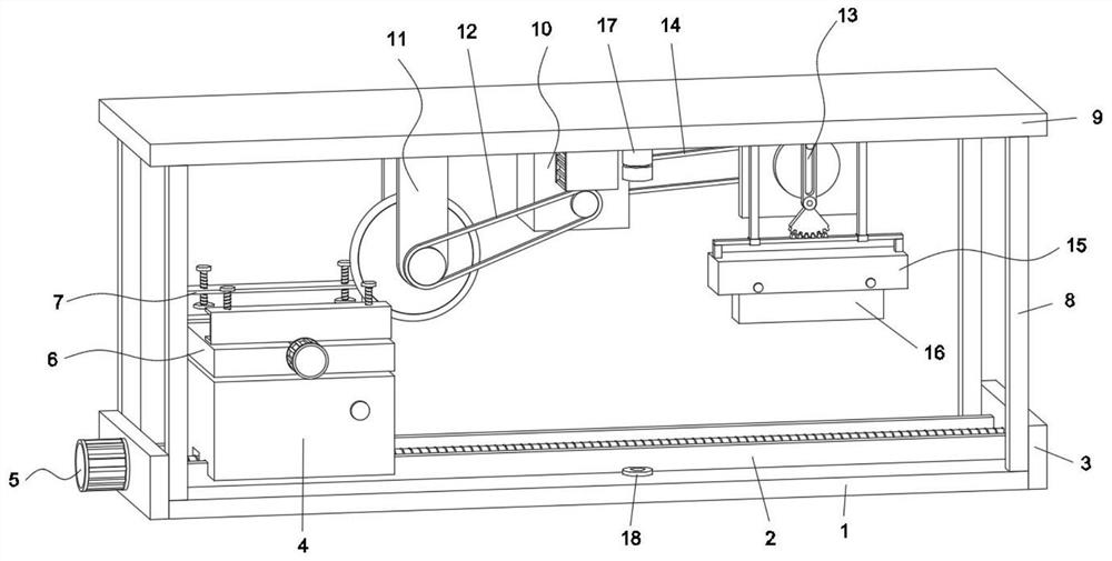
[0044] see figure 1 and Figure 9 , the present embodiment is a plate cutting machine, including a bottom plate 1, two guide rails 2 are symmetrically arranged on the top wall of the bottom plate 1, side plates 3 are fixed on both sides of the bottom plate 1, and a workbench 4 is slidably arranged on the guide rail 2, and the workbench 4 The bottom is provided with a driving assembly 5, the top of the workbench 4 is provided with a turntable 6, and the top of the turntable 6 is symmetrically provided with two clamping assemblies 7, the four corners of the top wall of the bottom plate 1 are fixed with columns 8, and the top of the column 8 is fixed with a top plate 9, Top plate 9 bottom wall is provided with cutting assembly 11, power assembly 10 and reciprocating assembly 13 successively, and power assembly 10 is connected cutting assembly 11 by first transmission belt 12, and power assembly 10 is connected reciprocating assembly 13 by second transmission belt 14, and reciproc...

Embodiment 2

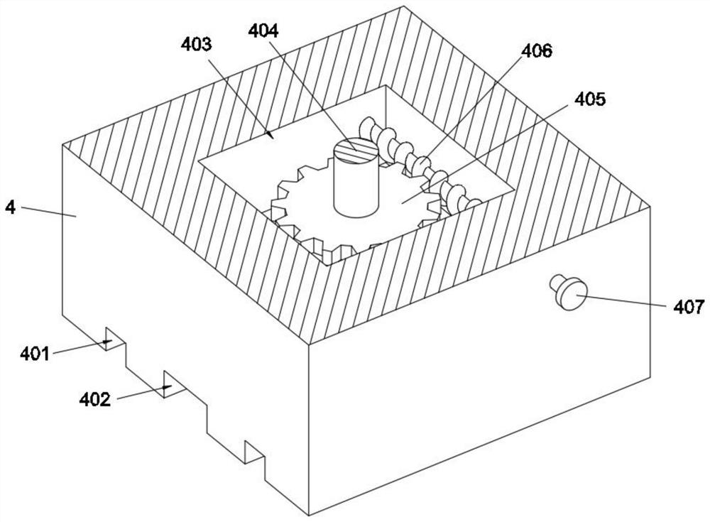
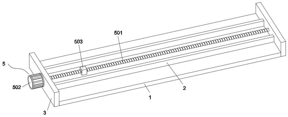
[0046] see Figure 2-3 , the bottom of the workbench 4 is provided with a guide groove 401 corresponding to the position of the guide rail 2, and the bottom of the workbench 4 is provided with a rectangular through groove 402 between the guide grooves 401, and a cavity 403 is provided in the workbench 4, and the cavity 403 is vertically rotated. There is a rotating shaft 404, a worm wheel 405 is fixed on the rotating shaft 404, and the worm wheel 405 is meshed with a worm 406, and the worm 406 is horizontally rotated and arranged in the cavity 403, and one end of the worm 406 passes through the side wall of the workbench 4 through a bearing and is fixed with a rotating knob 407. The top of the rotating shaft 404 runs through the top wall of the workbench 4 through bearings and is fixedly connected to the center of the bottom end of the turntable 6. The driving assembly 5 includes a screw 501, a first servo motor 502 and a screw block 503. The screw 501 is rotatably arranged bet...

Embodiment 3

[0048] see Figure 4 , the turntable 6 includes a platform body 601, a limit chute 602 is provided in the center of the top of the platform body 601, a bidirectional lead screw 603 is arranged for rotation in the limit chute 602, a second servo motor 604 is fixed on one side of the platform body 601, and the second The power output shaft of the servo motor 604 runs through the side wall of the table body 601 through bearings and is fixedly connected to one end of the two-way lead screw 603. The two ends of the two-way lead screw 603 are symmetrically screwed with two lead screw nuts 605, and the top of the lead screw nut 605 is fixed with a connecting clamp. Component7. The set turntable 6 can adapt to plates of different sizes within a certain range, and has strong practicability.


PUM


Abstract

The invention relates to the technical field of plate machining equipment, in particular to a plate cutting machine and a cutting method. The plate cutting machine comprises a bottom plate, wherein aguide rail is arranged on the top wall of the bottom plate, side plates are fixed to the two sides of the bottom plate, a workbench slidably is arranged on the guide rail, a driving assembly is arranged at the bottom of the workbench, a rotating table is arranged at the top of the workbench, a clamping assembly is arranged at the top of the rotating table, stand columns are fixed to the four corners of the top wall of the bottom plate, a top plate is fixed to the tops of the stand columns, a cutting assembly, a power assembly and a reciprocating assembly are sequentially arranged on the bottomwall of the top plate, a mounting block is fixed to the bottom of the reciprocating assembly, a grinding block is clamped to the bottom of the mounting block, a laser transmitter is fixed to the bottom wall of the top plate, and a laser receiver is fixed to the upper wall of the bottom plate. When the plate cutting device is used, the cutting angle of plates can be adjusted, the plates of different sizes can be clamped within a certain range, the application range is wide, the arranged power assembly can drive the cutting assembly and the reciprocating assembly to work, the use number of motors is reduced, energy consumption is reduced, and meanwhile the grinding block is convenient to replace.

Description

technical field [0001] The invention relates to the technical field of plate processing equipment, in particular to a plate cutting machine and a cutting method. Background technique [0002] Building material is a general term for materials used in civil engineering and construction engineering. Sheet material is a common material in building materials. Sheet material is a flat rectangular building material board made of standard size. It is used in the construction industry for walls, A component of a ceiling or floor. It also refers to forged, rolled or cast metal plates. Divided into thin plate, medium plate, thick plate, extra thick plate, usually made into flat rectangular building material plates of standard size. When using plates, it is often necessary to cut the plates according to the working conditions in order to adapt to the size and shape of the plate application environment. Plate cutting machine is a common machine for cutting plates, which cuts plates th...

Claims


Application Information

Patent Timeline
Patent Type & Authority Applications(China)
IPC IPC(8): B23P23/04
CPCB23P23/04
Inventor 杨妍
Owner 成都毅莘瑞科技有限公司
Why Eureka
Try Eureka