Pig bone self-rotating type cutting machine
A cutting machine and cutting mechanism technology, applied in metal processing and other directions, can solve the problems of danger, high safety factor, time-consuming and labor-intensive, etc., and achieve the effect of improving efficiency and reducing manpower
- Summary
- Abstract
- Description
- Claims
- Application Information
AI Technical Summary
Problems solved by technology
Method used
Image
Examples
Embodiment 1
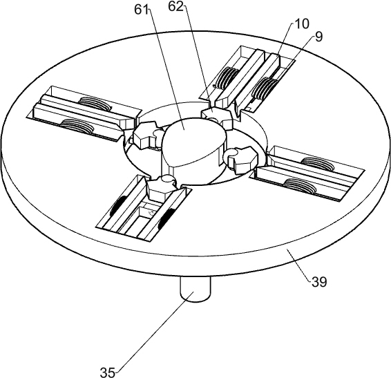
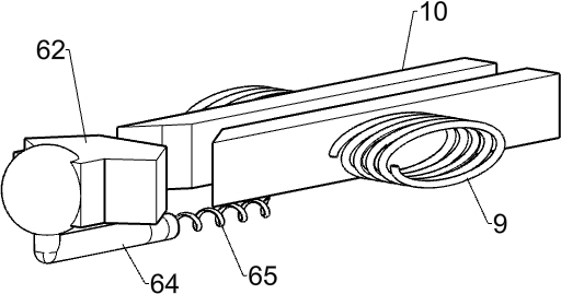
[0056] A kind of pork bone self-rotating cutting machine, such as figure 1 with 6 As shown, it includes a support table 1, a first motor 2, a rotating mechanism 3, a support table 4, a cutting mechanism 5, a discharge chamber 7, a fixed column 8, a second spring 9 and a pressure plate 10, and the middle part of the top right side of the support table 1 Connected with a support platform 4, the right side of the top of the support table 1 is connected with a first motor 2 by bolts, the first motor 2 is located on the left side of the support platform 4, a rotation mechanism 3 is connected between the first motor 2 and the support table 1, and the support platform 4 is connected with a cutting mechanism 5, the parts of the rotating mechanism 3 are evenly connected with a second spring 9, and the ends of the second spring 9 are connected with a pressure plate 10, and the left side of the top of the support table 1 is connected with a fixed column 8, and the left side of the fixed ...
Embodiment 2
[0059] On the basis of Example 1, such as figure 2 As shown, the rotating mechanism 3 includes a quarter gear 31, a first gear 32, a first support column 33, a flat belt assembly 34, a second support column 35, a limit block 36, a transmission disc 37, a transmission column 38 and The turntable 39, the top right side of the support table 1 is rotatably connected with the first support column 33, the first support column 33 is located on the left side of the first motor 2, the top of the first support column 33 is connected with the first gear 32, and the first motor 2 outputs A quarter gear 31 is connected to the shaft, and the quarter gear 31 meshes with the first gear 32. The top left side of the support table 1 is connected with a second support column 35, and the middle part of the second support column 35 is rotatably connected with a limit block. 36, a flat belt combination 34 is connected between the limiting block 36 and the first support column 33, the middle part of...
Embodiment 3
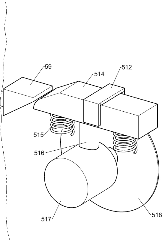
[0062] On the basis of Example 2, such as Figure 4-6 As shown, the cutting mechanism 5 includes a second gear 51, a transmission rod 52, a bearing seat 53, a bevel gear set 54, a first cam 55, a support shaft 56, an extrusion rod 57, a first spring 58, and a first wedge block 59. , support plate 510, limit frame 512, second wedge block 514, fourth spring 515, connecting rod 516, second motor 517 and cutting knife 518, support table 4 inner and lower sides are connected with bearing seat 53, on bearing seat 53 Rotationally connected with a transmission rod 52, the transmission rod 52 passes through the top of the support platform 4, the lower side of the transmission rod 52 is connected with a second gear 51, the second gear 51 meshes with the quarter gear 31, and the rear side of the support platform 4 top is connected There is a support shaft 56, the top of the support shaft 56 is rotatably connected with a first cam 55, a bevel gear set 54 is connected between the first cam...
PUM
 Abstract
Description
Claims
Application Information
 - R&D
- Intellectual Property
- Life Sciences
- Materials
- Tech Scout
- Unparalleled Data Quality
- Higher Quality Content
- 60% Fewer Hallucinations
Browse by: Latest US Patents, China's latest patents, Technical Efficacy Thesaurus, Application Domain, Technology Topic, Popular Technical Reports.
© 2025 PatSnap. All rights reserved.Legal|Privacy policy|Modern Slavery Act Transparency Statement|Sitemap|About US| Contact US: help@patsnap.com


