Injection molding machine for automobile spare part machining

A technology for spare parts and injection molding machines, which is applied in the field of injection molding machines for automobile spare parts processing, can solve the problems of insufficient qualification rate, easy to cause pauses, and complicated operation control, so as to improve product production efficiency, prevent excessive heating time, and speed up The effect of injection efficiency

Pending Publication Date: 2020-10-30
陈景伟
View PDF5 Cites 0 Cited by
  • Summary
  • Abstract
  • Description
  • Claims
  • Application Information

AI Technical Summary

Problems solved by technology

[0003] At present, most injection molding machines are screw-type structures. In one cycle of the injection molding machine, a certain amount of plastic can be heated and plasticized within a specified period of time, and then the molten plastic can be injected through the screw under a certain pressure and speed. In the mold cavity, after the injection is completed, the molten material injected into the cavity is kept in shape, but when the machine is just started up, it is necessary to heat the plastic particles in the material tube of the injection molding machine for a long time to make it into a sol, and the plastic particles are due to If the heating time is too long, the viscosity of the sol is low, the fluidity is good, and the product is easy to run. At the same time, after a period of production, the sol will continuously take away the heat in the material pipe, resulting in insufficient sol, excessive viscosity, and poor fluidity. , so that the product lacks glue, resulting in low product quality and insufficient pass rate. At the same time, in the screw injection molding machine, a single screw is used to transfer the sol and inject the sol. complex

Method used


Image

  • Injection molding machine for automobile spare part machining
  • Injection molding machine for automobile spare part machining
  • Injection molding machine for automobile spare part machining

Examples


Embodiment Construction

[0022] The following will clearly and completely describe the technical solutions in the embodiments of the present invention with reference to the accompanying drawings in the embodiments of the present invention. Obviously, the described embodiments are only some, not all, embodiments of the present invention. Based on the embodiments of the present invention, all other embodiments obtained by persons of ordinary skill in the art without making creative efforts belong to the protection scope of the present invention.

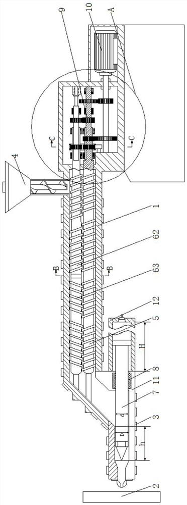
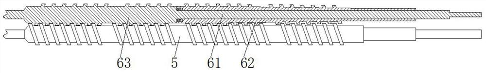
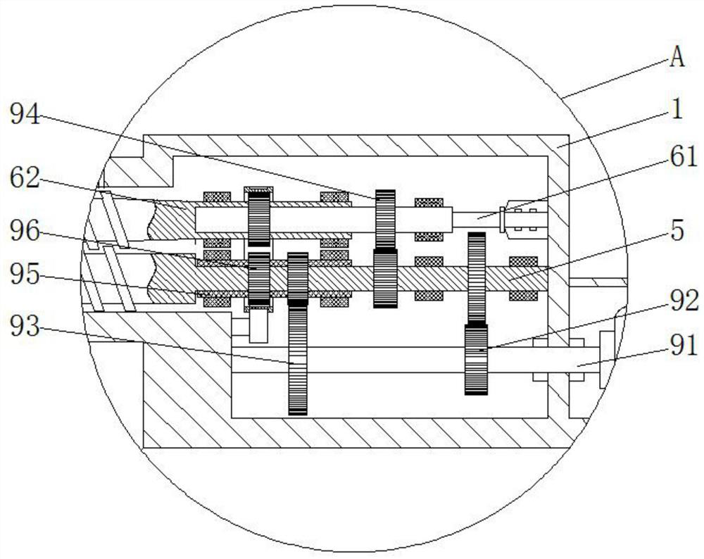
[0023] see Figure 1-5 , an injection molding machine for processing auto parts, comprising a fixed frame 1, a mold 2, a heating device 3 and a feeding device 4, the heating device 3 is fixedly installed on the fixed frame 1 and distributed evenly, and the feeding device 4 is fixedly connected to the fixed frame 1 And it is located in the middle of the upper surface of the fixed frame 1, the bottom of the left end of the fixed frame 1 is fixedly connected with...


PUM


Abstract

The invention relates to the technical field of automobile spare part production equipment, and discloses an injection molding machine for automobile spare part machining. The injection molding machine comprises a fixing frame, a mold, heating devices and a feeding device, wherein the heating devices are fixedly installed on the fixing frame and evenly distributed; the feeding device is fixedly connected with the fixing frame and positioned in the middle of the upper surface of the fixing frame; and an injection port is fixedly connected to the bottom of the left end of the fixing frame. Through the arrangement of a lower screw and an upper screw, plastic particles entering from the feeding device are sufficiently stirred and make uniform and sufficient contact with the wall of a materialbarrel, the melting speed of the plastic particles is increased, the heat efficiency of the heating devices is improved, and the heating cost is reduced; and meanwhile, through the arrangement of thematerial barrel shaped like a Chinese character 'zhong' in the fixing frame, the material barrel is matched with the lower screw and the upper screw, mixing of the plastic particles and sol is increased, the melting speed of the plastic particles is further increased, the situation that the viscosity is insufficient due to the fact that the sol heating time is too long is prevented, and then the product quality is improved.

Description

technical field [0001] The invention relates to the technical field of production equipment for auto parts, in particular to an injection molding machine for processing auto parts. Background technique [0002] Injection molding machine, also known as injection molding machine or injection machine, is the main molding equipment for making thermoplastic or thermosetting materials into various shapes of plastic products using plastic molding molds. The injection molding machine can heat the plastic and apply high pressure to the molten plastic to make it eject In recent years, injection molding machine manufacturers in industrially developed countries in the world have been continuously improving the function, quality, supporting capabilities, auxiliary equipment, and automation level of ordinary injection molding machines, and at the same time vigorously developing and developing large-scale injection molding machines. , special injection molding machines, reaction injection ...

Claims


Application Information

Patent Timeline
Patent Type & Authority Applications(China)
IPC IPC(8): B29C45/03B29C45/60B29C45/17B29C45/54
CPCB29C45/03B29C45/17B29C45/54B29C45/60B29C2045/1785
Inventor 不公告发明人
Owner 陈景伟
Why Eureka
Try Eureka