Winding assembly for continuous foaming material

A technology of winding components and foaming materials, applied in the direction of thin material processing, coiling strips, applications, etc., can solve problems affecting the quality and performance of plates, increasing the size deviation of finished products, and affecting work efficiency, etc.

Inactive Publication Date: 2020-10-30
ZHEJIANG RUNYANG NEW MATERIAL TECH
View PDF7 Cites 2 Cited by
  • Summary
  • Abstract
  • Description
  • Claims
  • Application Information

AI Technical Summary

Problems solved by technology

In the above process, the cooling and shaping process is particularly important, which determines the size deviation of the finished product, and there are many factors that affect the shaping effect, mainly in the following two aspects; one is the structural design of the cooling device itself, which directly reflects the precision level of the finished product size control. Cooling and shaping devices are mostly cooling rollers located outside the foaming furnace (such as CN105599210B, CN209111359U); the second is the effect of winding, because the sheet is relatively light and thin (usually only 2-3mm), the speed change during winding is easy to make it Changes in position and tension will affect the shaping effect and increase the size deviation of the finished product, especially in thickness. Foam materials usually need to be used on other boards. Once th

Method used


Image

  • Winding assembly for continuous foaming material
  • Winding assembly for continuous foaming material
  • Winding assembly for continuous foaming material

Examples


Embodiment 1

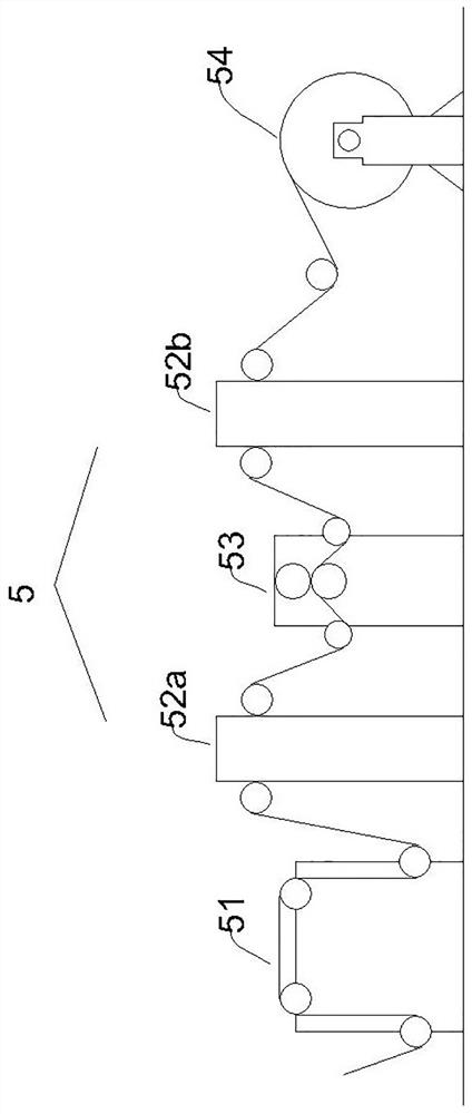
[0021] A winding assembly of continuous foam material such as figure 1 As shown, it includes a deviation correcting machine 51, a first tension machine 52a, a traction machine 53, a second tension machine 52b and a winding frame 54 arranged in sequence.

[0022] The deviation correcting machine 51 includes a frame and four rollers fixed on the frame. The deviation correcting machine 51 checks the correctness of the position through an infrared detector, and adjusts the direction of the frame through an automatic controller to correct the direction of foam material delivery. In order to avoid the influence of the deflection of the foam material on the thickness setting.

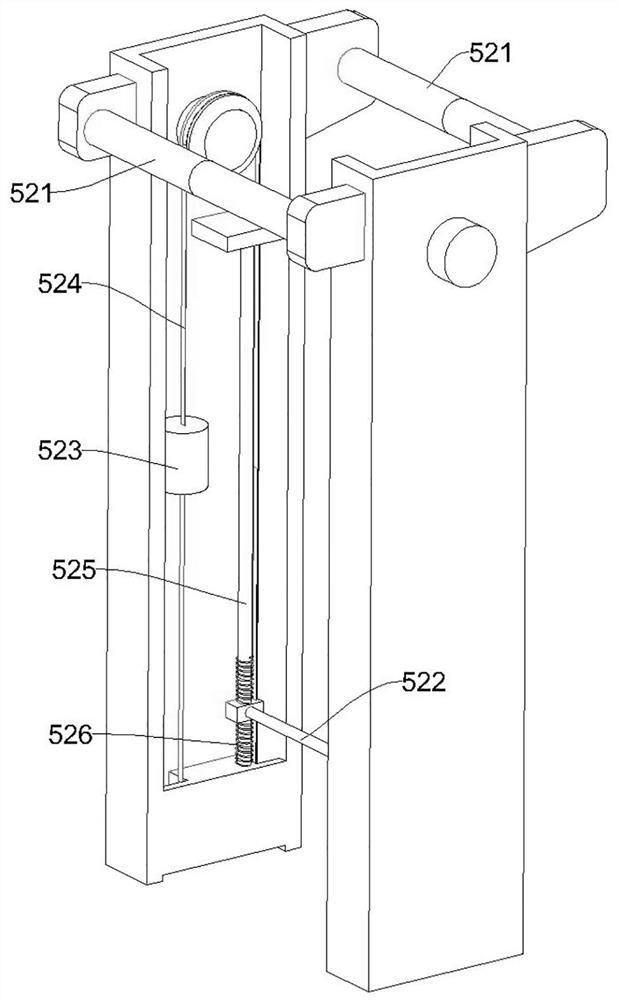
[0023] The structure of the first tension machine 52a is the same as that of the second tension machine 52b, as figure 2 As shown, it includes a floating roller 522 in the middle and two guide rollers 521 located on both sides of the floating roller 522 and above the floating roller 522. The guiding roller 5...

Embodiment 2

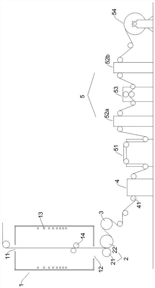
[0025] This embodiment is a preferred production system for the continuous foaming material comprising the winding assembly described in Embodiment 1, such as image 3 As shown, it includes a calibrating device, a cooling roll 3 , a corona machine 4 and a winding assembly 5 arranged in sequence.

[0026] The thickness fixing device includes a foaming chamber 1 and a thickness locking part 2; in the present embodiment, the foaming chamber 1 is a vertical foaming chamber, and the upper and lower ends are respectively provided with a feed port 11 and a discharge port 12. The inner wall of the bubble chamber 1 is provided with several heating elements 13 along the foaming material delivery direction, and the heating elements 13 are arranged in the middle part of the inner wall of the foaming furnace 1, and an unfolding roller 14 is arranged below the setting area of ​​the heating element 13, and the unfolding roller 14 is hollow inside, and is provided with cooling water inlet. T...


PUM


Abstract

The invention belongs to the technical field of foaming material production equipment, and particularly discloses a winding assembly for a continuous foaming material. The winding assembly comprises adeviation rectifying machine, a first tensioner, a traction machine, a second tensioner and a winding frame which are sequentially arranged. The first tensioner and/or the second tensioner comprise/comprises a floating roller and two guide rollers which are arranged on the two sides of the floating roller and further located above the floating roller. Drive parts are arranged at the two ends of the floating roller, and the floating roller can move up and down through the operation of the drive parts. By means of the winding assembly for the continuous foaming material, tension change and positional deviation caused by winding can be stably adjusted in time, winding can be completed without influencing shaping dimensional accuracy and the working efficiency is high.

Description

[0001] This application is a divisional application with application number 2020105716850, application date 2020.06.22, and invention name "a device for constant thickness of continuous foaming materials". technical field [0002] The invention belongs to the technical field of foaming material production equipment, and in particular relates to a continuous foaming material winding assembly. Background technique [0003] Sheet foaming refers to the process of heating a strip-shaped polymer material in a foaming furnace, and the foaming agent decomposes at high temperature to generate gas, fills the inside of the polymer material, and produces a foaming material with closed pores. In production, after the foaming is completed, the foaming material needs to be cooled and shaped by a cooling device, and then rolled directly or after some post-processing procedures (such as edge trimming, embossing, cutting, etc.) to obtain the finished product. In the above process, the cooling...

Claims


Application Information

Patent Timeline
IPC IPC(8): B65H23/038B65H23/26B65H23/02B65H23/04
CPCB65H23/038B65H23/26B29C44/203B29C44/3442B29C44/3415B29C44/60B29C59/10B29L2007/002
Inventor 万立祥杨庆锋张镤
Owner ZHEJIANG RUNYANG NEW MATERIAL TECH
Why Eureka
Try Eureka