Lifting movable heat treatment bell-type furnace

A bell furnace and lifting device technology, applied in heat treatment furnaces, heat treatment equipment, furnaces, etc., can solve the problems of cleaning, low furnace table edge loading strength, weak lifting stability, etc., to improve process preparation efficiency and heat treatment efficiency. , The effect of strong thermal insulation performance

Pending Publication Date: 2020-10-30
丹阳市恒泰电炉有限公司
View PDF0 Cites 3 Cited by
  • Summary
  • Abstract
  • Description
  • Claims
  • Application Information

AI Technical Summary

Problems solved by technology

It takes a long time to switch and load the hearth, and the processing efficiency of a single hearth is low
[0004] (2) The heat preservation performance of the hearth structure is average, the body structure strength of the hearth is low, the furnace loading strength of the edge of the hearth is low, the hearth is not strong and easy to deform and warp; the hearth structure cannot be quickly assembled, disassembled, replaced, and cleaned
Due to the generally large structure of bell-type furnaces, the heating mantle has a large mass and a long lifting stroke, and the lifting device of the bell-type furnace needs to have strong stability to ensure that the lifting process of the furnace mantle is stable. Among them, hydraulic cylinders are used for In the lifting device, although the structure is simple and easy to install, the connection stability between the hydraulic cylinder and the furnace cover structure is poor, and the lifting stability is weak when the stroke is long.

Method used


Image

  • Lifting movable heat treatment bell-type furnace
  • Lifting movable heat treatment bell-type furnace
  • Lifting movable heat treatment bell-type furnace

Examples


Embodiment Construction

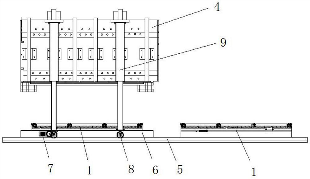
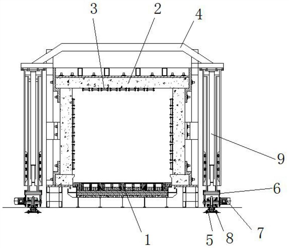
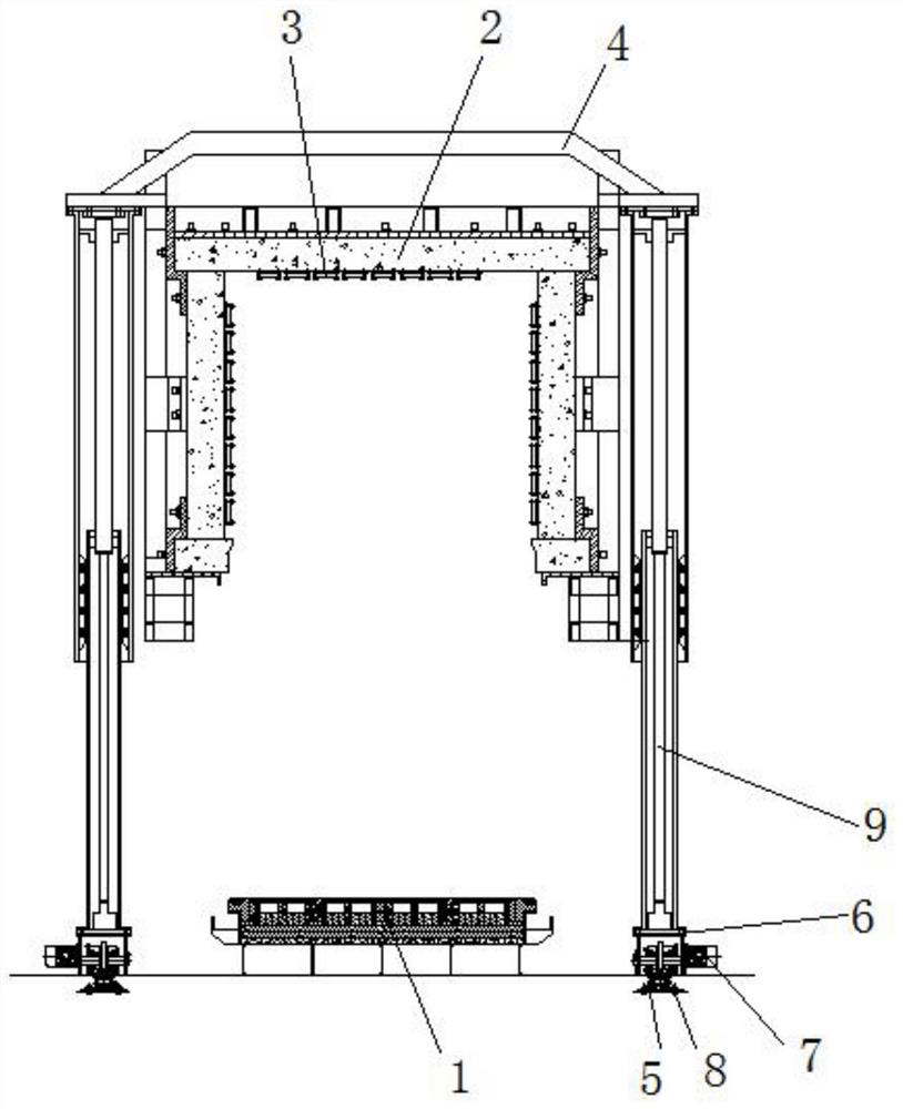
[0069] In order to make the technical solution of the present invention clearer, the present invention will be further described with reference to the accompanying drawings. Any solution obtained by equivalent replacement of the technical features of the technical solution of the present invention and conventional reasoning falls into the protection scope of the present invention. The fixing connection, fixing arrangement, and fixing structure mentioned in this embodiment are all well-known techniques known to those skilled in the art, such as gluing, welding, screw connection, bolt-nut connection, and riveting.

[0070] The driving motor mentioned in this embodiment adopts an ordinary stepping motor, and other similar products that can be purchased in the market can be used. The structure principle is a well-known technology well known to those in the field, and will not be repeated in the present invention.

[0071] As can be seen in conjunction with the drawings, a lifting mobile...


PUM


Abstract

The invention discloses a lifting movable heat treatment bell-type furnace. The furnace comprises furnace tables, a furnace lining, heating elements, a shell supporting structure, tracks, motor base frames, driving motors, rolling wheels and lifting devices; the two furnace tables are arranged, and are laterally arranged at an interval; the furnace lining is arranged above the furnace tables, andan embedded part is prefabricated in the furnace lining; the heating elements are wrapped around and suspended from the inner wall of a side furnace plate and the inner wall of a top furnace plate through corundum ceramic nails, and the shell supporting structure is wrapped around the outer wall of the furnace lining; and the tracks are arranged on the two sides of the furnace tables and are symmetrically arranged in parallel, the bottom surface of the track on each side is fixedly connected to the ground through bolts, the motor base frames are arranged on the top surfaces of the tracks in the same direction, the rolling wheels rotate with the motor base frames through rotating shafts, the driving motor is arranged on one side of the motor base frame of each side, and the lifting devicesare arranged on the two sides of the top surfaces of the motor base frames. According to the furnace, the same furnace cover is provided with two furnace table structures, the working efficiency is high, the heat preservation effect of the furnace tables is strong, the lifting devices are stable in structure, and the shell supporting structure is firm in structure.

Description

Technical field [0001] The invention relates to the field of bell-type furnaces, in particular to a lifting and moving heat treatment bell-type furnace. Background technique [0002] Bell-type furnaces are mostly used for annealing steel wires, steel pipes, copper strips, copper wires and silicon steel sheets in the metallurgical industry, and are used for batch heat treatment and heating of workpieces. The main structure of the bell-type furnace includes a furnace base, a furnace hood, a sealing structure, and a lifting structure. The existing bell furnace structure has the following technical defects: [0003] (1) The furnace base and the furnace hood of the bell-type furnace have a vertical lifting structure, that is, one furnace structure corresponds to a furnace hood structure. When the furnace base is loaded for heat treatment, the furnace hood needs to be raised, and then the furnace hood is lowered after the loading is completed. , Realize a heat treatment process. The s...

Claims


Application Information

Patent Timeline
IPC IPC(8): C21D9/00
CPCC21D9/00C21D9/0006
Inventor 吴海军
Owner 丹阳市恒泰电炉有限公司
Why Eureka
Try Eureka