
Lining device for epitaxial reaction chamber and epitaxial reaction chamber

A reaction chamber and epitaxy technology, applied in the direction of chemical reactive gas, crystal growth, coating, etc., can solve the problems of difficult adjustment, uneven air flow field, affecting the surface process of silicon wafer 107, etc., to achieve uniform distribution, improve Process effect, performance index uniform and controllable effect

Active Publication Date: 2020-10-30
BEIJING NAURA MICROELECTRONICS EQUIP CO LTD
View PDF7 Cites 2 Cited by
  • Summary
  • Abstract
  • Description
  • Claims
  • Application Information

AI Technical Summary

Problems solved by technology

[0007] 2. Reference image 3 , the interior of the reaction chamber 106 is circular in cross-section, and the interior is provided with a silicon chip 107. The arrangement direction of the gas guide grooves 104 on the lower backing ring 102 points to the center of the circle in the radial direction, so that the process gas cannot flow through the reaction chamber along a parallel straight line. 106
Because the gas guide groove 104 points to the center of the circle in the radial direction, when the gas enters the inside of the process chamber 107 after leaving the gas guide groove, it will tend to gather toward the center, and then the gas will disperse and hit the inner wall of the arc-shaped chamber. Bounce back and disturb the airflow field (refer to image 3 ), affecting the surface process of the silicon wafer 107
Especially for larger silicon wafers, the gas flow field is not uniform and difficult to adjust at the edge of the wafer

Method used


Image

  • Lining device for epitaxial reaction chamber and epitaxial reaction chamber
  • Lining device for epitaxial reaction chamber and epitaxial reaction chamber
  • Lining device for epitaxial reaction chamber and epitaxial reaction chamber

Examples


Embodiment Construction

[0044]The present invention will be described in more detail below with reference to the accompanying drawings. Although preferred embodiments of the invention are shown in the drawings, it should be understood that the invention may be embodied in various forms and should not be limited to the embodiments set forth herein. Rather, these embodiments are provided so that this disclosure will be thorough and complete, and will fully convey the scope of the invention to those skilled in the art.

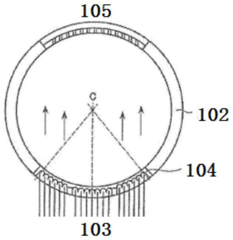
[0045] Figure 4 A schematic diagram of the overall structure of a lining device for an epitaxial reaction chamber according to an embodiment of the present invention is shown.

[0046] Such as Figure 4 As shown, a lining device for an epitaxial reaction chamber includes: an upper lining ring 1 and a lower lining ring 2, the upper lining ring 1 is placed above the lower lining ring 2 and coaxially arranged with the lower lining ring 2;

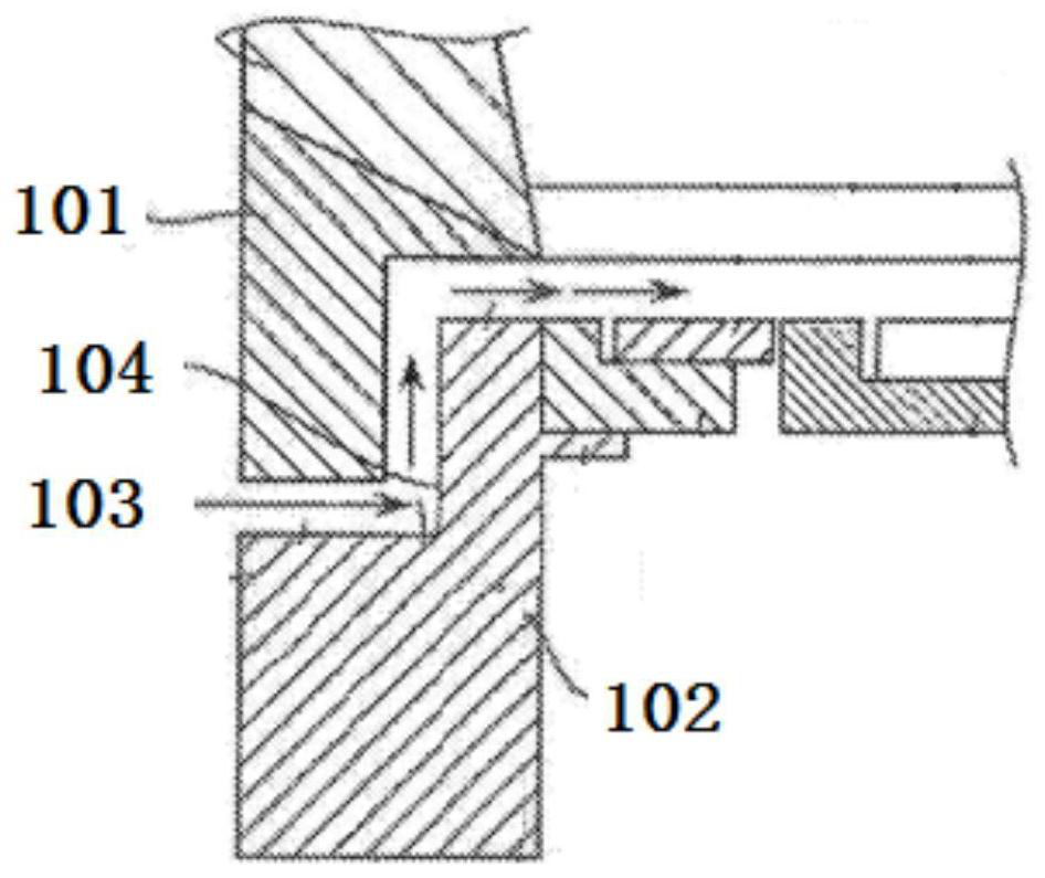
[0047] combine Figure 5 to Figure 8 As show...


PUM

PropertyMeasurementUnit
thicknessaaaaaaaaaa

Abstract

The invention discloses a lining device for an epitaxial reaction chamber and the epitaxial reaction chamber. The lining device comprises a lower lining ring and an upper lining ring which is arrangedabove the lower lining ring and is coaxial with the lower lining ring, wherein a gas guide groove and a gas discharge groove are formed in the face, facing the upper lining ring, of the lower liningring, the gas guide groove and the gas discharge groove are oppositely formed in the circumferential direction of the lower lining ring, an angle is formed between the gas guide direction of the gas guide groove and the axial direction of the lower lining ring, the upper lining ring comprises a ring body, a first extending part and a second extending part, the first extending part and the second extending part are arranged on the ring body, the first extending part extends towards the gas guide groove from the outer edge of the ring body to match with the lower lining ring to form a gas inletpart, and the second extending part extends towards the gas discharge groove from the outer edge of the ring body to match with the lower lining ring to form a gas discharge part. The situation that agas flow field entering a process chamber is smoother and more uniform is achieved, and the epitaxial process effect is improved.

Description

technical field [0001] The invention relates to the technical field of semiconductor equipment, and more specifically, to a lining device for an epitaxial reaction chamber and the epitaxial reaction chamber. Background technique [0002] During the epitaxial growth process, the uniformity of the gas flow field in the chamber has a great influence on various indicators of the epitaxial layer. [0003] According to the reaction mechanism of chemical vapor deposition (CVD) process technology, it can be known that there must be a uniformly distributed gas flow field and concentration field near the substrate surface in order to obtain excellent epitaxial process results. According to the requirements of uniform doping and uniform thickness required for CVD growth films, it is required that only the reactants and dopants transported to various parts of the substrate surface are at the same rate during the growth process, and the gas flow field maintains a uniform parallel laminar...

Claims


Application Information

Patent Timeline
Patent Type & Authority Applications(China)
IPC IPC(8): C23C16/455C23C16/44C30B25/14C30B25/08
CPCC23C16/45504C23C16/4412C30B25/14C30B25/08
Inventor 袁福顺李晓军
Owner BEIJING NAURA MICROELECTRONICS EQUIP CO LTD
Learn More