Sample rod for transmission electron microscope system and corresponding transmission electron microscope system

A transmission electron microscope and sample rod technology, applied in scanning probe technology, instruments, etc., can solve the problem of unable to measure the spectroscopic properties of materials synchronously

Active Publication Date: 2020-10-30
INST OF PHYSICS - CHINESE ACAD OF SCI
View PDF6 Cites 4 Cited by
  • Summary
  • Abstract
  • Description
  • Claims
  • Application Information

AI Technical Summary

Problems solved by technology

[0005] The purpose of this technology is to solve the technical problem that the current transmission electron microscopy technology cannot simultaneously measure the spectral properties of materials, so as to realize the in situ study of the microstructure and properties of materials

Method used


Image

  • Sample rod for transmission electron microscope system and corresponding transmission electron microscope system
  • Sample rod for transmission electron microscope system and corresponding transmission electron microscope system
  • Sample rod for transmission electron microscope system and corresponding transmission electron microscope system

Examples


Embodiment 2

[0049] The present invention also provides a method for optical focusing and automatic scanning using the above-mentioned TEM system for optical focusing and automatic scanning (or the application of the above-mentioned sample rod in the TEM system), said method comprising the following steps:

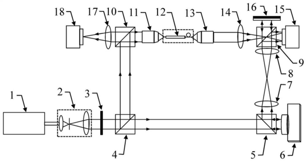
[0050] Step 1: The linearly polarized light emitted by the laser 1 first passes through the beam expander collimator 2 to become parallel light, and then passes through a half-wave plate 3 to adjust the polarization state of the parallel light, that is, to change the s-polarized light and p-polarized light The ratio of light to adjust the intensity of the two polarized light;

[0051] Step 2: Divide the parallel light obtained in step 1 into two beams through the polarization beam splitter prism 4, one of which is used as the reference light wave and the other as the object light wave, for example, the transmitted p-polarized light is used as the reference light wave, and the reflected ...


PUM


Abstract

The invention provides a sample rod for a transmission electron microscope system. The sample rod is characterized in that the sample rod (12) comprises a front end head and a sample rod body, the first end of the front end head is connected with the sample rod body, a sample is installed at the second end of the front end head, and an optical fiber (21) which extends from one end of the sample rod body to the other end of the sample rod body and faces the sample on the front end head is arranged in the sample rod body. According to the transmission electron microscope system provided by the invention, firstly, laser is divided into object light waves and reference light waves through a polarization splitting prism; the object light waves and the reference light waves are subjected to off-axis interference at the image acquisition device after passing through the optical fiber of the sample rod, conjugate phase information of the object light waves is obtained through numerical reconstruction and is loaded to a spatial light modulator, time reversal of the light waves is realized, and laser focusing and automatic scanning of the light waves are realized in the transmission electronmicroscope system.

Description

technical field [0001] The invention relates to the technical field of transmission electron microscopy, and more specifically, to a sample rod for a transmission electron microscope system and a corresponding transmission electron microscope system. Background technique [0002] Exploring the correspondence between the atomic structure and electronic structure of materials and their physical properties is one of the most important tasks in condensed matter physics research, and it is still a challenge in experimental technology. Spectroscopy technology can be used to study the spectrum generation of materials and their interaction with matter. It is a direction that has always been valued in natural science research and has important application prospects, such as dynamical processes and atomic energy level structures. The development of ultra-high spatial resolution spectroscopy characterization technology to measure and study the microscopic mechanism of the excited state...

Claims


Application Information

Patent Timeline
IPC IPC(8): G01Q30/02G01Q30/20
CPCG01Q30/02G01Q30/20
Inventor 马超杰刘畅刘开辉王恩哥白雪冬
Owner INST OF PHYSICS - CHINESE ACAD OF SCI
Why Eureka
Try Eureka