Sintering equipment, sintering annealing method of battery and battery

A technology for sintering equipment and batteries, applied in circuits, photovoltaic power generation, electrical components, etc., can solve the problem of high equipment cost

Pending Publication Date: 2020-10-30
RISEN ENERGY (CHANGZHOU) CO LTD
View PDF1 Cites 2 Cited by
  • Summary
  • Abstract
  • Description
  • Claims
  • Application Information

AI Technical Summary

Problems solved by technology

[0009] In order to overcome the deficiencies of the prior art, one of the purposes of the present invention is to provide a sintering equipment, which can solve the problem of high equipment cost in the prior art when the battery preparation process improves the passivation performance of the N-type TOPCon battery
[0010] The second object of the present invention is to provide a battery sintering and annealing me...

Method used


Image

  • Sintering equipment, sintering annealing method of battery and battery
  • Sintering equipment, sintering annealing method of battery and battery
  • Sintering equipment, sintering annealing method of battery and battery

Examples


Embodiment 1

[0035] Based on the N-type TOPCon battery, the annealing process of the N-type TOPCon battery can be realized without changing the sintering equipment used in the sintering process in the existing battery preparation method, and the passivation performance of the battery can be improved; at the same time, no additional equipment is required Therefore, while ensuring the improvement of the passivation performance of the battery, the problem in the prior art that additional annealing equipment needs to be added to achieve annealing, which leads to an increase in equipment cost, is reduced.

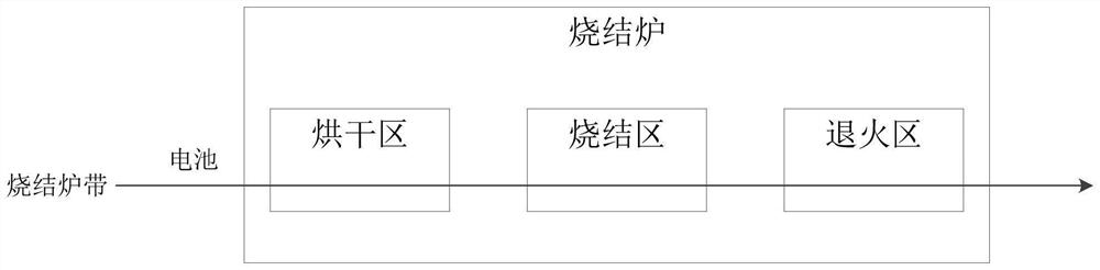
[0036] like figure 1 As shown, the present invention provides a sintering equipment, the sintering equipment is provided with a drying area, a sintering area and an annealing area.

[0037] Among them, the drying area is used to realize the drying process of the battery. The sintering area is used to realize the sintering process of the battery. The annealing area is used to realize the an...

Embodiment 2

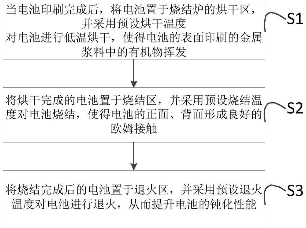
[0051] like figure 2 As shown, the present invention provides a battery sintering annealing method, which is applied to a sintering device provided in Example 1, and the method includes the following steps:

[0052] Step S1. After the battery printing is completed, place the screen-printed battery in the drying zone of the sintering furnace, and dry the battery at a preset drying temperature, so that the organic matter in the metal paste printed on the surface of the battery Volatile.

[0053] Step S2, placing the dried battery in a sintering zone, and sintering the battery at a preset sintering temperature, so that the front and back of the battery form a good ohmic contact.

[0054] Step S3, placing the sintered battery in an annealing zone, and annealing the battery at a preset annealing temperature, thereby improving the passivation performance of the battery.

[0055] Preferably, the drying temperature is 200°-500°.

[0056] Preferably, the preset sintering temperatur...

Embodiment 3

[0103] Preferably, the present invention also provides a method for preparing a battery, which includes the sintering and annealing method for preparing the battery as provided in Embodiment 1 of the present invention.


PUM


Abstract

The invention discloses sintering equipment which is used for preparing a battery, and the battery is an N-type TOPCon battery. A drying area, a sintering area and an annealing area are arranged in the sintering equipment; the drying area is used for drying a battery subjected to silk-screen printing, so that organic matters in slurry printed on the surface of the battery are volatilized; the sintering area is used for sintering the dried battery, so that good ohmic contact is formed on the surface of the battery; and the annealing area is used for annealing the sintered battery, so that the passivation performance of the battery is improved. According to the invention, the passivation performance of the battery can be improved on the basis of not increasing extra annealing equipment. Theinvention also provides a sintering annealing method of the battery and the battery.

Description

technical field [0001] The invention relates to a battery preparation process, in particular to a sintering device, a battery sintering annealing method and the battery. Background technique [0002] N-type TOPCon battery (Tunnel Oxide Passivated Contact, tunnel oxide passivated contact battery) has been a hot spot in industry research in the past two years. Generally speaking, the front structure of an N-type TOPCon battery is the same as that of an N-type PERT battery (Passivated Emitter and Rear totally-diffused Cell, passivated emitter and rear fully-diffused cell), but the back structure of an N-type TOPCon battery is the same as that of an N-type PERT battery. The back structure of the battery is not the same, but is composed of a tunnel oxide layer, a doped polysilicon layer, and a passivation film. At the same time, using a structure composed of a tunneling oxide layer, a doped polysilicon layer, and a passivation film as the back structure of an N-type TOPCon batte...

Claims


Application Information

Patent Timeline
IPC IPC(8): H01L21/67H01L31/18H01L31/042
CPCH01L21/67098H01L31/1864H01L31/042Y02E10/50Y02P70/50
Inventor 庄宇峰崔艳峰袁声召万义茂林海峰
Owner RISEN ENERGY (CHANGZHOU) CO LTD
Why Eureka
Try Eureka