Rotor finish machining full-automatic production line and rotor finish machining full-automatic production process

A production line, fully automatic technology, used in the manufacture of stator/rotor bodies, etc., which can solve problems such as inflow of substandard products, assembly deviation, and restrictions

Pending Publication Date: 2020-10-30
浙江东精智能装备有限公司
View PDF2 Cites 3 Cited by
  • Summary
  • Abstract
  • Description
  • Claims
  • Application Information

AI Technical Summary

Problems solved by technology

There will be a series of processing procedures during the finishing treatment of the rotor, such as pretreatment of the rotor, installation of balance weights at both ends of the rotor, etc. At present, these series of procedures are completed manually in a single step, and none of them is complete. The automatic production line has low processing efficiency, high labor demand, high cost and output not meeting the demand
[0003] At present, when the rotor is pretreated in the factory, most of the rotors are deburred, sanded, reamed and positioned manually, so a large amount of manual operations are required on a production line to complete the operation, which increases the production cost. , and manual operation is used, there will be unqualified products flowing into the subsequent process, and rework will be required in the later stage, the labor intensity is high, the production efficiency is reduced, and the product quality cannot be guaranteed;
[0004] At present, when installing balance weights at both ends of the rotor, it is necessary to manually install the upper and lower balance weights on the rotor, and then use a press to 
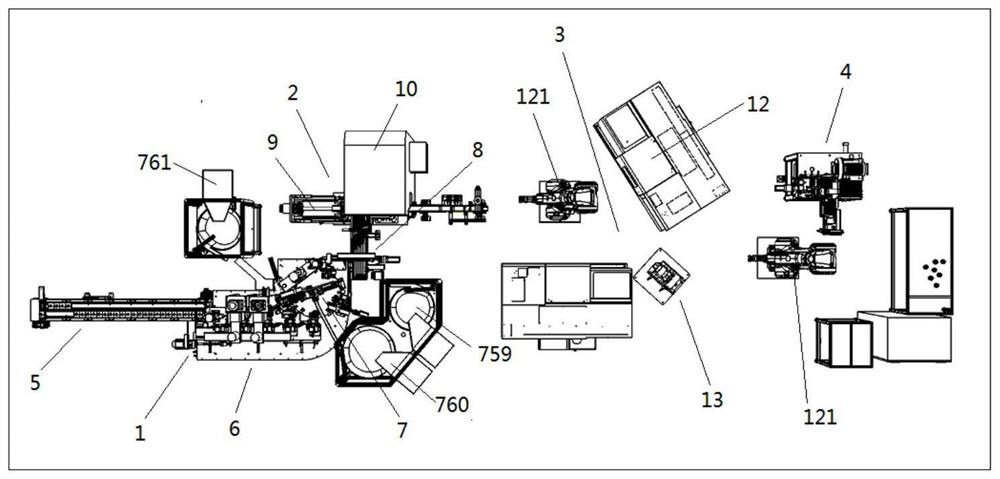
crimp the rotor and the upper and lower balance weights, which is inefficient and dangerous; the existing publication number is CN109201902A. An automatic production line for rotor pressure riveting is described in the paper, which includes an assembly stand, riveting assembly, main balance weight vibration plate, gear oil cap vibration plate, auxiliary balance weight vibration plate, rotor detection and positioning device and Transplanting mechanism; the riveting assembly is set in the middle of the assembly bench for riveting the rotor; the main balance weight vibrating plate is set on the assembly bench and on the right side of the riveting assembly for conveying the main balance block; the oil retaining cap The vibrating plate is set on the assembly stand and is located at the rear end of the riveting assembly, which is used for conveying gear oil caps; the rotor detection and positioning device is set on the assembly stand, and is located on the left side of the riveting assembly, for detecting and positioning the rotor; the auxiliary balance The block vibrating plate is set on the assembly stand, and is located at the rear end of the rotor detection and positioning device, and is used to transport the auxiliary balance weight; the transplanting mechanism is set on the assembly stand, and is located at the front end of the rotor detection and positioning device, for transplanting the rotor; However, there is no pretreatment mechanism for the rotor in this production, and the processing of the rotor in the previous process will produce corresponding burrs and other problems, so that the burrs and other problems in the subsequent processing will affect the automatic assembly of the flat and horizontal blocks. It will cause assembly deviation, which will have a great hidden danger to product quality;
[0005] After the balance weights at both ends of the rotor are installed, in order to ensure the coaxiality between the balance weight and the rotor, the rotor is generally shaped. Most of the shaping machines in the prior art use hydraulic or pneumatic devices to test the pressure of the rotor. Carry out shaping, and only one side of the rotor can be pressed and shaped during shaping, it is difficult to ensure the coaxiality of the rotor, so the effect of shaping is poor and the efficiency is low; the existing publication number is CN205986532U which discloses a rotor shaping machine. A rotor shaping machine is disclosed, which includes a body and a track-changing stepping device arranged on the top of the body, a guide rail and a shaping device, the guide rail is horizontally arranged on the body, and the shaping device is located directly above the guide rail , the track-changing stepping device is located on the body on the right side of the material guide track and adopts a flow-through structure design, so that the rotor shaping process is automatically completed by the equipment, which effectively improves the processing efficiency, but the shaping machine is suitable for a single Processing, and only one-sided stamping of the rotor, but the shaping effect of this method is not good, the coaxiality cannot meet the requirements, the shaping effect is poor, and the efficiency is low, which has great hidden dangers to the quality of the product;
[0006] When the outer diameter of the rotor is finished, it is generally measured manually, and then the tool compensation is modified on the lathe according to the size to ensure the finished size. However, the efficiency of manual measurement is low, and there are differences in measurement technology. Therefore, There are still great hidden dangers to the quality of the product. Finally, in order to ensure the size and surface roughness of the product, it is generally necessary to polish the rotor. The efficiency of manual processing is low, and the quality is limited by the manual technology of the operator.

Method used


Image

  • Rotor finish machining full-automatic production line and rotor finish machining full-automatic production process
  • Rotor finish machining full-automatic production line and rotor finish machining full-automatic production process
  • Rotor finish machining full-automatic production line and rotor finish machining full-automatic production process

Examples


Embodiment Construction

[0075] Below we combine the Figure 1-39 A fully automatic production line and production process for rotor finishing described in the present invention will be further described.

[0076] like figure 1 As shown in , a fully automatic production line for rotor finishing in this embodiment is characterized by an operation control system, a pretreatment system 1, a shaping system 2, a finishing system 3 and a polishing detection system 4; the pretreatment system 1 includes The feeding mechanism 5, the pretreatment mechanism 6 docked with the feeding mechanism, and the balance weight assembly mechanism 7 cooperating with the pretreatment mechanism 6; the shaping system 2 includes a coding conveying mechanism 8, a feeding mechanism docked with the coding conveying mechanism 9. A shaping mechanism 10 for shaping the rotor and an output mechanism 11 docked with the shaping mechanism 10 to facilitate the shaping of the rotor; the finishing system 3 includes a finishing mechanism 12 ...


PUM


Abstract

The invention discloses a rotor finish machining full-automatic production line and a rotor finish machining full-automatic production process. The rotor finish machining full-automatic production line is characterized by comprising a pretreatment system, a shaping system, a finish machining system and a polishing detection system, wherein the pretreatment system comprises a feeding mechanism, a pretreatment mechanism for pretreating a rotor and a balance block assembling mechanism for mounting a balance block on the rotor; the shaping system comprises a code printing conveying mechanism, a feeding mechanism, a shaping mechanism for shaping the rotor and an output mechanism after the rotor is shaped; the shaping mechanism is used for shaping the rotor; the finish machining system comprisesa finish machining mechanism for conducting finish machining on the outer diameter of the rotor and a detection compensation mechanism. Through cooperative use of the pretreatment system, the shapingsystem, the finish machining system and the polishing detection system, a complete full-automatic production line is formed for rotor finish machining, the automation degree is high, the product quality is good, the consistency degree is high, the efficiency is high, the labor demand is greatly reduced, and the labor cost is greatly reduced.

Description

technical field [0001] The invention relates to a rotor finishing production line, in particular to an automatic rotor finishing production line and a production process. Background technique [0002] Motor rotor: Also the rotating part in the motor. The motor consists of two parts, the rotor and the stator, which are used to realize the conversion of electrical energy and mechanical energy and mechanical energy and electrical energy. There will be a series of processing procedures during the finishing treatment of the rotor, such as pretreatment of the rotor, installation of balance weights at both ends of the rotor, etc. At present, these series of procedures are completed manually in a single step, and none of them is complete. The automatic production line has low processing efficiency, high labor demand, high cost and output not meeting the demand. [0003] At present, when the rotor is pretreated in the factory, most of the rotors are deburred, sanded, reamed and pos...

Claims


Application Information

Patent Timeline
Patent Type & Authority Applications(China)
IPC IPC(8): H02K15/02
CPCH02K15/02
Inventor 蒋利锋
Owner 浙江东精智能装备有限公司
Why Eureka
Try Eureka