An electron source

An electron source and electron technology, applied in the field of electron source, can solve problems such as excessive downtime and shorten life, and achieve the effect of high electron emission rate

Pending Publication Date: 2020-10-30
ISOTOPX LTD
View PDF6 Cites 3 Cited by
  • Summary
  • Abstract
  • Description
  • Claims
  • Application Information

AI Technical Summary

Problems solved by technology

Operating the heated filament/cathode of the electron source at higher temperatures shortens t

Method used


Image

  • An electron source
  • An electron source
  • An electron source

Examples


Embodiment Construction

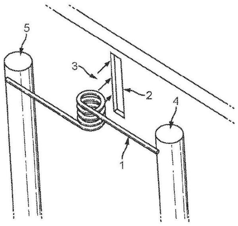
[0053] Figure 1AAn electron source for a gas source mass spectrometer according to the prior art is schematically shown. The electron source comprises a tungsten wire coil 1 having opposite respective wire ends electrically connected to a current input terminal 4 having a first potential and having a second potential different from the first. The current output terminal 5 of two potentials, so that the current flows through the wire coil 1 . Enough current flows to heat the tungsten wire coil (eg, hotly) to a temperature sufficient for the surface of the wire coil to thermally emit electrons from its surface. That is, the thermal energy obtained by the electrical heating effect of the current through the wire coil is sufficient to energize the electrons in the wire coil to obtain energy in excess of the surface work function of the wire coil.

[0054] Although electrons are emitted substantially omnidirectionally from the wire coil 1, those electrons emitted in the preferre...


PUM


Abstract

An electron source in a gas-source mass spectrometer the electron source comprising: an electron emitter cathode presenting a thermionic electron emitter surface in communication with a gas-source chamber of the gas-source mass spectrometer for providing electrons there to; a heater element electrically isolated from the electron emitter cathode and arranged to be heated by an electrical current therein and to radiate heat to the electron emitter cathode sufficient to liberate electrons thermionically from said electron emitter surface, therewith to provide a source of electrons for use in ionising a gas the gas-source chamber.

Description

technical field [0001] The present invention relates to electron sources for providing electrons, eg, in mass spectrometers, such as gas source mass spectrometers. Background technique [0002] Many scientific instruments rely on the ionization of gas molecules in order to prepare the molecules for subsequent manipulation. Electron beam bombardment is commonly used for this process. Electrons are generated by thermionic emission from the cathode, these electrons are accelerated through the space containing the gas molecules, and collisions between the electrons and the gas molecules ionize a part of the molecules. [0003] Conventional ion sources typically use tungsten filaments arranged in various geometries (eg ribbons, coils) where the filament also acts as a cathode and emits electrons from its surface. However, although this design is easy to manufacture, it has significant disadvantages that limit its performance. These disadvantages include but are not limited to ...

Claims


Application Information

Patent Timeline
IPC IPC(8): H01J49/08H01J49/14H01J1/28H01J27/20
CPCH01J1/28H01J27/205H01J49/08H01J49/147H01J1/22
Inventor 达米安·保罗·图特尔安东尼·迈克尔·琼斯
Owner ISOTOPX LTD
Why Eureka
Try Eureka