
Automatic deslagging conveying belt of earth pressure balance shield machine

A technology of automatic slag removal and earth pressure balance, which is applied to conveyor objects, transportation and packaging, cleaning devices, etc., can solve the problems of high maintenance and use cost of conveyor belts, large surface wear of smooth belts, and difficult transportation of smooth belts. , to achieve the effect of quick and smooth removal of slag, reduce wear and improve slag carrying capacity

Inactive Publication Date: 2020-11-03
CHINA CREC RAILWAY ELECTRIFICATION BUREAU GRP
View PDF6 Cites 1 Cited by
  • Summary
  • Abstract
  • Description
  • Claims
  • Application Information

AI Technical Summary

Problems solved by technology

[0002] During the excavation process of the earth pressure balance shield machine, due to the large water content in the formation, more than 80% of the intervals contain groundwater, and about 50% of the intervals are completely located in groundwater, resulting in the excavation process. The amount of water is large, and the belt frame at the spiral exit has a certain angle (the inclination angle is 10°), so it is difficult to transport the traditional earth pressure balance shield machine with a smooth belt
Moreover, in order to improve the transportation efficiency of the smooth belt, the conveyor belt is usually equipped with a scraper that abuts against the outer surface of the smooth belt of the conveyor belt, thereby removing the muck on the surface of the smooth belt in real time. This muck removal method The surface wear of the smooth belt is relatively large, and the maintenance cost of the conveyor belt is relatively high

Method used


Image

  • Automatic deslagging conveying belt of earth pressure balance shield machine
  • Automatic deslagging conveying belt of earth pressure balance shield machine
  • Automatic deslagging conveying belt of earth pressure balance shield machine

Examples


Embodiment Construction

[0041] Embodiments of the technical solutions of the present invention will be described in detail below in conjunction with the accompanying drawings. The following examples are only used to illustrate the technical solutions of the present invention more clearly, and therefore are only examples, rather than limiting the protection scope of the present invention.

[0042] It should be noted that, unless otherwise specified, the technical terms or scientific terms used in this application shall have the usual meanings understood by those skilled in the art to which the present invention belongs.

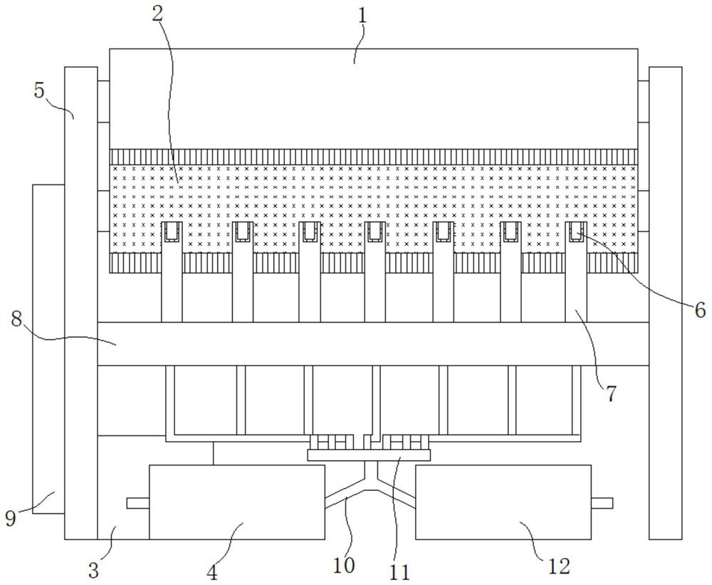
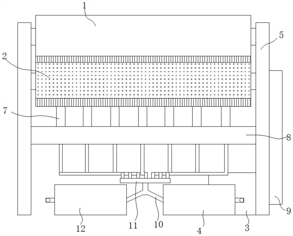
[0043] Such as figure 1 and Figure 5 As shown, an automatic slag removal conveyor belt 1 for an earth pressure balance shield machine, including a conveyor belt 1;

[0044] The belt outer surface of the conveyor belt 1 is provided with a plurality of herringbone protrusions 13 along its extending direction;

[0045] A brush roller is arranged across the bottom of the rear part of...


PUM


Abstract

The invention discloses an automatic deslagging conveying belt of an earth pressure balance shield machine. The automatic deslagging conveying belt comprises a conveying belt body. A plurality of herringbone protrusions are arranged on the outer surface of a belt of the conveying belt body in the extending direction of the belt. A brush roller is arranged at the position, close to the output end of the conveying belt body, below the rear portion of the conveying belt body in a crossing manner, the brush roller is driven by a motor located below the rear portion of the conveying belt body to rotate in the direction of the output end of the conveying belt body, and bristles of the brush roller abut against the outer surface of the belt of the conveying belt body. An automatic steam flushingdevice used for automatically flushing the brush roller is further included. According to the conveying belt, the slag carrying capacity is improved, much is removed quickly and smoothly, and the maintenance and use cost of the conveying belt body is effectively reduced.

Description

technical field [0001] The invention relates to an earth pressure balance shield machine conveyor belt, in particular to an earth pressure balance shield machine automatic slag removal conveyor belt. Background technique [0002] During the excavation process of the earth pressure balance shield machine, due to the large water content in the formation, more than 80% of the intervals contain groundwater, and about 50% of the intervals are completely located in groundwater, resulting in the excavation process. The amount of water is large, and the belt frame at the spiral outlet has a certain angle (the inclination angle is 10°), so it is difficult to transport the traditional earth pressure balance shield machine with a smooth belt. Moreover, in order to improve the transportation efficiency of the smooth belt, the conveyor belt is usually equipped with a scraper that abuts against the outer surface of the smooth belt of the conveyor belt, thereby removing the muck on the sur...

Claims


Application Information

Patent Timeline
IPC IPC(8): B65G45/18B65G45/22
CPCB65G45/18B65G45/22
Inventor 祁宝成幸智军李清宪王建伟朱明辉王润超芦建广秦朋飞刘瑞雷志权李国华吴永毅史强吉帅科
Owner CHINA CREC RAILWAY ELECTRIFICATION BUREAU GRP
Learn More