Compressor, control method and air conditioner

A compressor and control valve technology, applied in the field of compressors, can solve the problem that the bearing temperature cannot be guaranteed at the same time, and will not be too high, and achieve the effect of avoiding excessive suction superheat and reducing the temperature

Active Publication Date: 2020-11-03
ZHUHAI GREE REFRIGERATION TECH CENT OF ENERGY SAVING & ENVIRONMENTAL PROTECTION
View PDF6 Cites 2 Cited by
  • Summary
  • Abstract
  • Description
  • Claims
  • Application Information

AI Technical Summary

Problems solved by technology

[0005] Therefore, the technical problem to be solved by the present invention is to overcome the defects that the compressor in the prior art cannot simultaneously ensure that the bearing temperature will not be too high and the superheat of the suction air will not be too high during operation, so as to provide a compressor machine, control method and air conditioner

Method used


Image

  • Compressor, control method and air conditioner
  • Compressor, control method and air conditioner
  • Compressor, control method and air conditioner

Examples


Embodiment 1

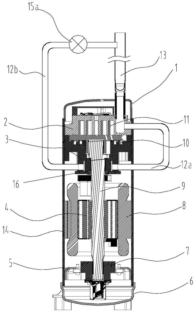
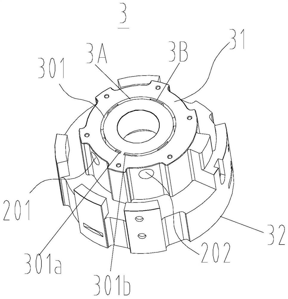
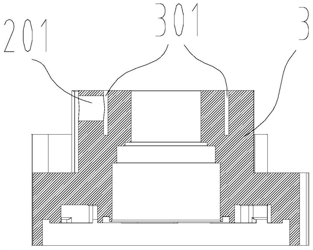
[0045] Embodiment one, in figure 1 Here, the present invention sets a first bypass pipeline 12a and a second bypass pipeline 12b outside the compressor. The side through hole 401 of the fixed scroll 2 communicates with the suction port 501 above the fixed scroll 2 (such as Figure 4 and Figure 5 ). Air inlet 201 and air outlet 202 are provided on the side of upper support 3, and a cooling chamber (inner channel 301) coaxial with the bearing hole is set on upper support 3, and air inlet 201 and air outlet 202 communicate with the cooling chamber ( Such as image 3 ), the cooling chamber is not connected at the gas inlet 201 and the gas outlet 202 where the gas travel arc is small (that is, the internal channel is not fully connected, and the cross section is a superior arc structure), after the gas enters the cooling chamber through the inlet 201 , it is necessary to go through a larger arc to leave the cooling chamber from the air outlet 202. The cooling chamber is divide...

Embodiment 2

[0046] Embodiment two, Figure 7 It is a schematic diagram of the overall structure of an alternative embodiment, and a second control valve 15b (preferably a one-way valve) is provided on the first bypass line 12a. Figure 8 It is a schematic diagram of the second implementation case of the bearing cooling chamber of the upper bracket, which communicates with the air inlet 201 and the air outlet 202 of the upper bracket 3 respectively, and the cooling chamber is located at the place where the air inlet 201 and the air outlet 202 have a smaller gas travel arc. If it is not connected, after the gas enters the cooling chamber through the air inlet 201, it needs to go through a large arc to leave the cooling chamber from the air outlet 202. The cooling chamber is a circular groove, Figure 9 It is a system schematic diagram of an alternative embodiment. The specific working principle is that after the refrigerant flows out of the evaporator, part of the refrigerant directly enter...


PUM


Abstract

The invention provides a compressor, a control method and an air conditioner. The compressor comprises a static vortex plate, an upper support and a bearing, the static vortex plate is provided with an air suction port and a side through hole, and the side through hole communicates with the air suction port; the compressor further comprises an air suction pipe, a first bypass pipeline and a secondbypass pipeline, and one end of the air suction pipe communicates with the air suction port; the first end of the first bypass pipeline communicates with the side through hole, the second end of thefirst bypass pipeline can guide air to the upper support, the third end of the second bypass pipeline can introduce the air from the upper support, and the fourth end of the second bypass pipeline communicates with the air suction pipe; or the fourth end of the second bypass pipeline communicates with the air suction pipe, the third end of the second bypass pipeline can guide the air to the uppersupport, the second end of the first bypass pipeline can introduce the air from the upper support, and the first end of the first bypass pipeline communicates with the side through hole. According tothe compressor, an external pipeline is led out from each of the side wall of the air suction pipe and the side wall of the static vortex plate of the compressor, so that the cooling effect of the upper support bearing is achieved, meanwhile, the overhigh air suction superheat degree is avoided, and the operation reliability of the compressor is improved.

Description

technical field [0001] The invention relates to the technical field of compressors, in particular to a compressor, a control method and an air conditioner. Background technique [0002] Scroll compressors are widely used in the fields of refrigeration, air conditioning and heat pumps because of their high efficiency, small size, light weight, and stable operation. Generally speaking, a scroll compressor is composed of a closed shell, a fixed scroll, a movable scroll, a bracket, a crankshaft, an oil supply device for an anti-rotation mechanism, and a motor. The profiles of the movable and static scrolls are both spiral , The movable scroll is installed eccentrically with respect to the static scroll with a difference of 180°, so multiple crescent-shaped spaces are formed between the movable and static scrolls. When the movable scroll takes the center of the static scroll as the center of rotation and performs non-rotation-translational motion with a certain radius of rotatio...

Claims


Application Information

Patent Timeline
Patent Type & Authority Applications(China)
IPC IPC(8): F04C18/02F04C29/04F04C29/00F04C29/12F04C23/02F04C28/26F04C28/28
CPCF04C18/0215F04C18/0261F04C29/04F04C29/12F04C29/00F04C23/02F04C28/26F04C28/28F04C2240/10
Inventor 魏会军罗鸿智刘双来李海港
Owner ZHUHAI GREE REFRIGERATION TECH CENT OF ENERGY SAVING & ENVIRONMENTAL PROTECTION
Why Eureka
Try Eureka