Proximity Type Large Aperture Ratio Microchannel Plate Type Photomultiplier Tube

A technology of photomultiplier tube and microchannel plate, which is applied in the direction of electron multiplier tube, electron multiplier anode device, electron multiplier detailed information, etc. It can solve the problem of large proportion of dead zone area, limited size, unreasonable design of external dimensions, etc. problem, to achieve the effect of reducing the dead zone area

Active Publication Date: 2022-07-08
NORTH NIGHT VISION TECH
View PDF6 Cites 0 Cited by
  • Summary
  • Abstract
  • Description
  • Claims
  • Application Information

AI Technical Summary

Problems solved by technology

[0002] With the development of science and technology, high-energy physics, high-end nuclear medical instruments and other fields put forward higher and higher requirements for photomultiplier tubes. Second order, and a single photomultiplier tube cannot be used alone due to its limited size. Many photomultiplier tubes need to be spliced ​​into a detection area array facing the detection area. Therefore, extremely high requirements are placed on the dimensions of the photomultiplier tubes. For example, the design of the dimensions is unreasonable. , on the one hand, it is not suitable for large-area splicing, on the other hand, after splicing is completed, the proportion of dead zone area is too large, which affects the effective detection area
[0003] Due to the low position resolution and large dead zone of traditional photomultiplier tubes, it is increasingly unable to meet the application requirements in many fields

Method used


Image

  • Proximity Type Large Aperture Ratio Microchannel Plate Type Photomultiplier Tube
  • Proximity Type Large Aperture Ratio Microchannel Plate Type Photomultiplier Tube
  • Proximity Type Large Aperture Ratio Microchannel Plate Type Photomultiplier Tube

Examples


Embodiment Construction

[0034] In order to better understand the technical content of the present invention, specific embodiments are given and described below in conjunction with the accompanying drawings.

[0035] Aspects of the invention are described in this disclosure with reference to the accompanying drawings, in which a number of illustrative embodiments are shown. Embodiments of the present disclosure are not necessarily intended to include all aspects of the invention. It should be understood that the various concepts and embodiments described above, as well as those described in greater detail below, can be implemented in any of a variety of ways, as the concepts and embodiments disclosed herein do not limited to any implementation. Additionally, some aspects of the present disclosure may be used alone or in any suitable combination with other aspects of the present disclosure.

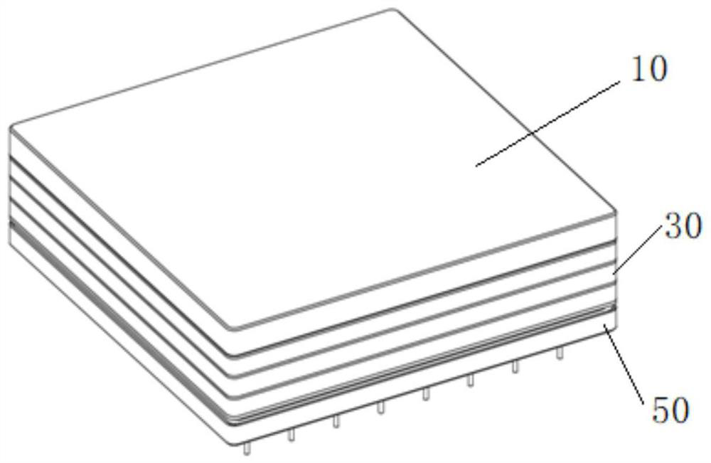
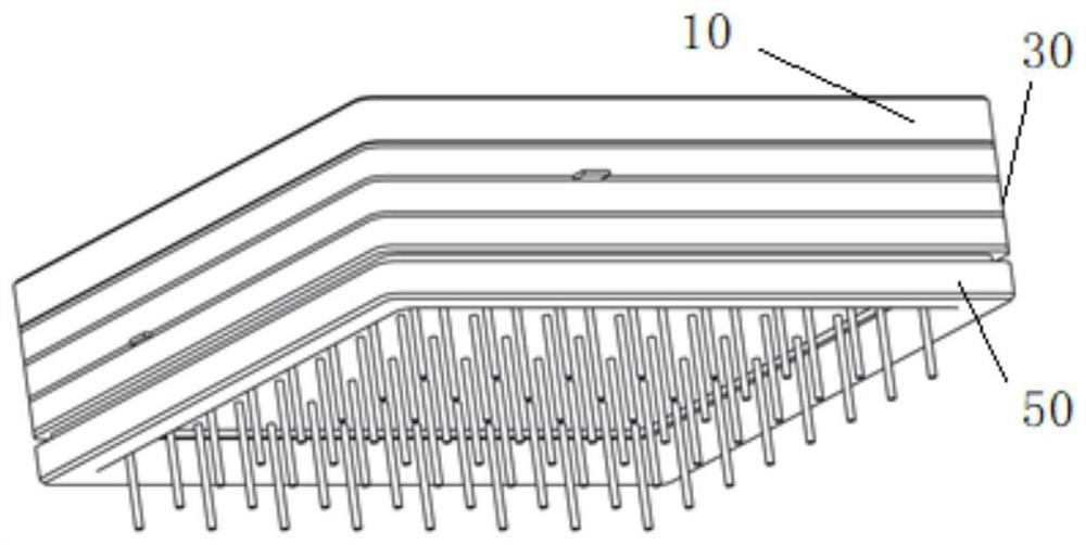
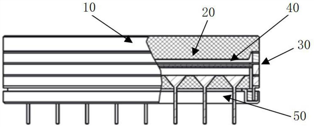
[0036] combine Figure 1-Figure 7 The illustrated example embodiment of a close-fitting large open area rati...


PUM

PropertyMeasurementUnit
thicknessaaaaaaaaaa
angleaaaaaaaaaa

Abstract

The invention provides a close-fitting large opening area ratio microchannel plate photomultiplier tube, which comprises an input light window, a photocathode, a square tube shell, a microchannel plate and a position-sensitive anode. The photocathode is located on the inner surface of the input light window, and the microchannel plate is located between the photocathode and the position-sensitive anode; the square tube shell includes a first ceramic ring, an input electrode, a second ceramic ring, a getter electrode, a third The ceramic ring and the indium sealing layer, the square tube shell is sealed with the input light window through the sealing layer; the position-sensitive anode includes a ceramic skeleton, an output electrode and an anode, and a plurality of anodes are distributed in the ceramic skeleton in a matrix array, and the anodes are mutually Disconnected and independent of each other; each anode has a conical structure, the electron receiving end is a square surface, and the output end gradually transitions from a conical to a cylindrical anode rod. The aperture of the microchannel plate is in the shape of "く", one end is positioned and powered by the input electrode, and the other end is positioned by the output electrode.

Description

technical field [0001] The invention relates to the technical field of microchannel plates, in particular to a close-fitting large opening area ratio microchannel plate type photomultiplier tube. Background technique [0002] With the development of science and technology, high-energy physics, high-end nuclear medical instruments and other fields have put forward higher and higher requirements for photomultiplier tubes. The position resolution capability of photomultiplier tubes needs to reach the sub-millimeter level, and the signal response and time resolution need to reach picometers. It is on the order of seconds, and a single photomultiplier tube cannot be used alone due to its limited size. Many photomultiplier tubes are required to face the detection area and spliced ​​into a detection surface array. Therefore, extremely high requirements are also placed on the outer dimensions of the photomultiplier tubes, such as unreasonable outer dimension design. , on the one han...

Claims


Application Information

Patent Timeline
Patent Type & Authority Patents(China)
IPC IPC(8): H01J43/28H01J43/12H01J43/24
CPCH01J43/28H01J43/12H01J43/246
Inventor 王兴超徐海洋司曙光顾燕黄国瑞任玲吴凯金真王宁汤偲晨
Owner NORTH NIGHT VISION TECH
Why Eureka
Try Eureka