
Cross-flow air cooling rotor and high-speed motor

An air-cooled, high-speed motor technology, applied in the direction of cooling/ventilation devices, electromechanical devices, electrical components, etc., can solve the problems of uneven cooling and poor cooling effect, and achieve good energy saving effect, enhanced heat dissipation effect, and improved cooling efficiency Effect

Inactive Publication Date: 2020-11-03
SHANGHAI RES INST OF CHEM IND +1
View PDF7 Cites 2 Cited by
  • Summary
  • Abstract
  • Description
  • Claims
  • Application Information

AI Technical Summary

Problems solved by technology

[0004] The purpose of the present invention is to provide a high-speed motor with rotor cross-flow air cooling to solve the problem of poor cooling effect and uneven cooling of the air cooling system of the high-speed motor

Method used


Image

  • Cross-flow air cooling rotor and high-speed motor

Examples


Embodiment 1

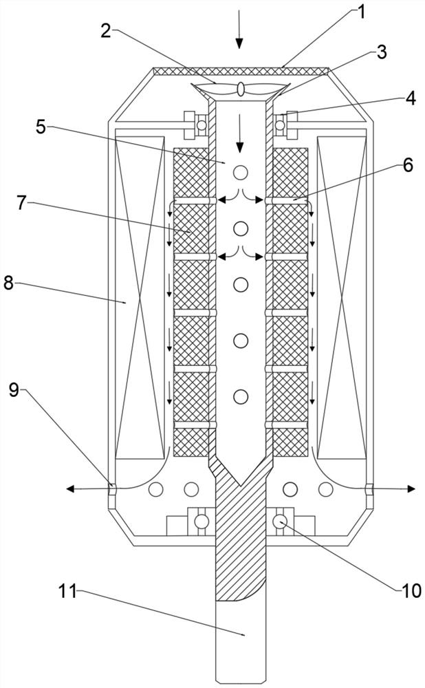
[0038] see figure 1 As shown, this embodiment provides a cross-flow air-cooled rotor, including a hollow shaft 5 with a hollow interior, and a permanent magnet rotor 7 sleeved on the hollow shaft 5. One end of the hollow shaft 5 is open, and the other end is The output shaft 11 of the high-speed motor is fixedly connected, and the permanent magnet rotor 7 is also provided with several cooling centrifuge tubes connected to the inner cavity of the hollow shaft 5 .

[0039] In this embodiment, the cooling air centrifuge tubes 6 are arranged in a staggered axial direction along the hollow shaft 5 . A staggered parallel arrangement is preferred. This setting can make full use of the centrifugal force brought by the rotation to drive the cooling air flow to achieve the cooling effect; the heat dissipation effect is more uniform and local overheating is avoided. The opening position of the hollow shaft 5 is also provided with a compressor turbine 2 , and when the compressor turbine...

Embodiment 2

[0041] Such as figure 1 As shown, the present embodiment provides a high-speed motor with rotor cross-flow air cooling, including a casing, a hollow shaft 5, a permanent magnet rotor and a stator 8. The hollow shaft 5 is hollow inside, and its two ends pass through bearings respectively (that is, corresponding to the front and rear respectively) The end is the front bearing 4 and the rear bearing 10) supported in the housing, and one end of the hollow shaft 5 is open, and the other end is fixedly connected to the output shaft 11 of the high-speed motor. The permanent magnet rotor is sleeved on the hollow shaft 5 and fixed on the hollow shaft 5. The stator 8 on the inside of the casing is installed on the coaxial center line, and the permanent magnet rotor 7 is also provided with a plurality of cooling gas centrifuge tubes 6 that penetrate radially, leaving a gap between the permanent magnet rotor 7 and the stator 8 .

[0042] In this embodiment, the cooling air centrifugal tubes...


PUM


Abstract

The present invention relates to a cross-flow air cooling rotor and a high-speed motor. The high-speed motor comprises a shell, a hollow shaft, a permanent magnet rotor and a stator, the interior of the hollow shaft is hollow, the two ends of the hollow shaft are supported and arranged in the shell through bearings respectively, one end of the hollow shaft is open, and the other end of the hollowshaft is fixedly connected with an output shaft of the high-speed motor. The permanent magnet rotor sleeves the hollow shaft, the permanent magnet rotor and the stator fixed to the inner side of the shell are coaxially installed, the permanent magnet rotor is further provided with a plurality of cooling air centrifugal tubes which are communicated in the radial direction, and a gap is reserved between the permanent magnet rotor and the stator. Compared with the prior art, the problems of poor cooling effect and non-uniform cooling of an air heat dissipation system of the high-speed motor are solved, and the high-speed motor can be cooled by adopting an open-circuit hybrid ventilation cooling system.

Description

technical field [0001] The invention belongs to the technical field of high-speed motors, and relates to a cross-flow air-cooled rotor and a high-speed motor. Background technique [0002] In modern times, the application of motors has been very extensive, and most of them use higher electromagnetic loads to improve the utilization of materials. When the motor runs at high speed, it will generate a lot of heat. If the heat generated is not cooled, it will reduce the magnetism of the fixed magnet, and it is more likely to further reduce the electromagnetic properties of the fixed capital coil, reducing or losing the performance of the motor. In order to deal with these problems, although there are cooling methods such as water cooling, oil cooling, and hydrogen cooling, none of them have the low cost and wide application of air cooling. [0003] For example, Chinese patent CN209402316U discloses a motor with a cooling system, which includes a casing, and a rotor and a stator...

Claims


Application Information

Patent Timeline
Patent Type & Authority Applications(China)
IPC IPC(8): H02K1/32H02K9/06H02K1/27
CPCH02K1/32H02K9/06H02K1/2706
Inventor 蒋凯董学胜薛晓康张小沁王思怿冷远鹏
Owner SHANGHAI RES INST OF CHEM IND
Learn More