
Eureka
For R&D, Eureka makes reading and utilizing patents & technical documents easy.
Eureka AIR
Designed for self-driven R&D workflows. Generate viable solutions, solve complex R&D challenges, empower your innovation with AI.

Eureka Materials
Designed for material experts only. Revolutionize your material R&D, from search, analyze, to developing new materials.

TechResearch
Generate reliable direction feasibility study reports for your R&D in just a few steps.

TechSeek
Discover and master advanced knowledge NOW. Basics, ideas, possibilities, all at once.

TechMind
As an expert in R&D Theories, TechMind can generates customized viable solutions instantly.

TechRisk
Analyze your overall solution with one click, know your potential R&D risks in advance.

TechMonitor
Get weekly tech updates, stay abreast of the latest tech innovations and key insights.
Slitting machine for lithium battery
A technology of slitting machine and lithium battery, applied in the direction of lithium storage battery, secondary battery manufacturing, non-aqueous electrolyte storage battery, etc., can solve the problems of inability to move forward, battery leakage, deformation of metal lithium plate, etc. , reduce the uneven effect
- Summary
- Abstract
- Description
- Claims
- Application Information
AI Technical Summary
Problems solved by technology
Method used
Image

Examples
Embodiment 1
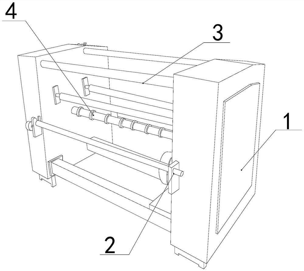
[0027] as attached figure 1 to attach Figure 5 Shown:
[0028] The invention provides a slitting machine for lithium batteries, the structure of which includes a frame 1, a winding shaft 2, a support rod 3, and a slitting roller 4. The winding shaft 2 is fixed on the middle and lower part of the front of the frame 1, and the support rod 3 is embedded and fixed between the frames 1, and the slitting roller 4 is installed in the middle part of the inner side between the frames 1.
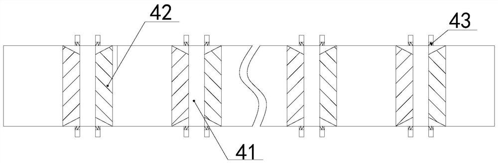
[0029] The slitting roller 4 is provided with a blade 41 , a fixed block 42 , and a clamping block 43 . Both sides of the blade 41 are fixed on the surface of the slitting roller 4 by the fixing block 42 .
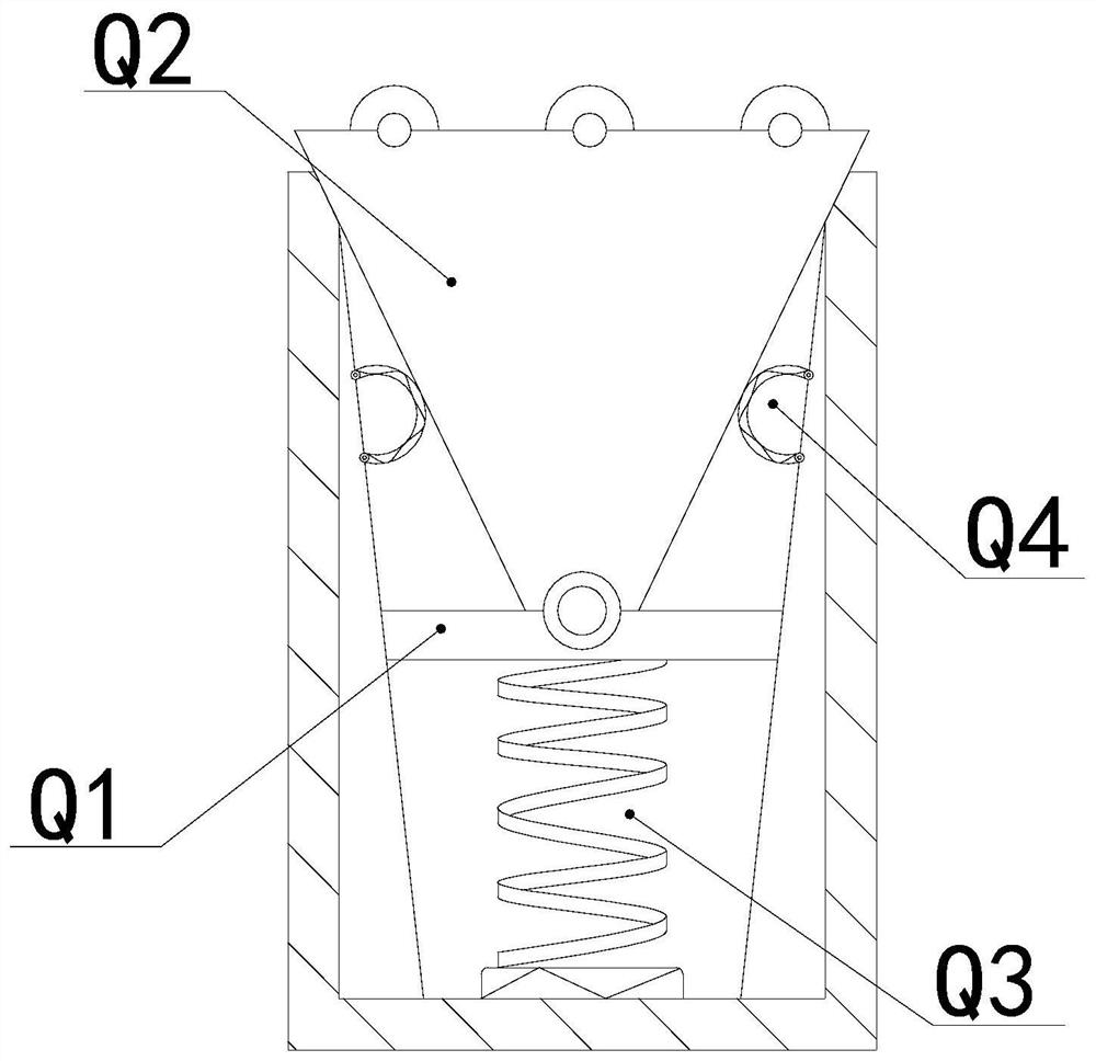
[0030] Wherein, the clamping block 43 is provided with a clamping plate Q1, a top block Q2, a spring Q3, and a spring ring Q4, the clamping plate Q1 is arranged inside the clamping block 43, and the bottom is connected with the spring Q3, and the top block Q2 runs through The top and bottom of...
Embodiment 2
[0036] as attached Image 6 to attach Figure 8 Shown:
[0037] Wherein, the ejector rod W5 is provided with locking teeth R1, feed inlet R2, support plate R3, bullet block R4, connecting rod R5, brush plate R6, and the support plate R3 is vertically fixed in the middle of the ejector rod W5, so The clamping teeth R1 are respectively installed on the middle and lower parts of both sides of the support plate R3, and the clamping teeth R1 run through both sides of the ejector rod W5, the feed inlet R2 is recessed on the surface of the clamping teeth R1, and the elastic block R4 is arranged in the support plate R3 On both sides of the upper part, the bottom of the connecting rod R5 is connected to the top of the elastic block R4, the brush plate R6 is respectively fixed on both ends of the connecting rod R5, and there are two locking teeth R1, which are triangular in shape and have a smooth surface The inclined surface accelerates the falling burrs along the surface from the feed...
PUM
 Abstract
Description
Claims
Application Information
 - R&D Engineer
- R&D Manager
- IP Professional
- Industry Leading Data Capabilities
- Powerful AI technology
- Patent DNA Extraction
Browse by: Latest US Patents, China's latest patents, Technical Efficacy Thesaurus, Application Domain, Technology Topic, Popular Technical Reports.
© 2024 PatSnap. All rights reserved.Legal|Privacy policy|Modern Slavery Act Transparency Statement|Sitemap|About US| Contact US: help@patsnap.com