Knee joint driven by flexible driver

A flexible driver and knee joint technology, applied in the field of bionic robots, can solve problems such as difficult control, large hysteresis, and low driving speed

Active Publication Date: 2020-11-10
JILIN UNIV
View PDF7 Cites 9 Cited by
  • Summary
  • Abstract
  • Description
  • Claims
  • Application Information

AI Technical Summary

Problems solved by technology

They exhibit good performance in terms of strain and force, however, low actuation speed, large hysteresis, and difficult control are their main disadvantages

Method used


Image

  • Knee joint driven by flexible driver
  • Knee joint driven by flexible driver
  • Knee joint driven by flexible driver

Examples


Embodiment Construction

[0053] The present invention will be described below with reference to the accompanying drawings.

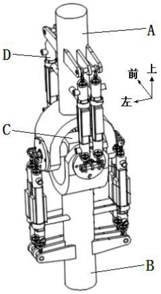
[0054] like figure 1 , Figure 18 and Figure 19 As shown, the present invention consists of a bionic femur A, a bionic tibia B, a bionic cruciate ligament C, and a flexible actuator D, wherein the bionic femur A and the bionic tibia B are arranged up and down, and the bionic cruciate ligament C is located at the bionic femoral condyle 29 and the bionic femur A of the bionic femur A. Between the bionic tibial condyles 38 of the tibia B.

[0055] The outer ring of the anterior bearing 14 in the artificial cruciate ligament C is connected with the anterior hole 52 of the bionic tibia B; the outer ring of the middle and posterior bearing 16 of the artificial cruciate ligament C is connected with the middle and posterior hole 37 of the bionic tibia B by interference; the middle left of the artificial cruciate ligament C The outer ring of the bearing 15 is connected with the left h...


PUM


Abstract

The invention discloses a knee joint driven by a flexible driver, and belongs to the technical field of biomimetic robots. According to the knee joint driven by the flexible driver, a biomimetic femurand a biomimetic tibia are arranged up and down, a simulated cruciate ligament is positioned between a biomimetic femoral condyle of the biomimetic femur and a biomimetic tibial condyle of the biomimetic tibia, and the biomimetic femur and the biomimetic tibia are separately provided with two bionic muscle pairs. Bionic muscle is attached to a biomimetic tendon and is fixed to a fixed ring. According to the knee joint driven by the flexible driver, super-spiral silver-plated nylon fibers are integrated into one driving unit to be applied to the knee joint, the spiral silver-plated nylon fibers are driven by electric heat to contract, and high-response, lag-free and easily-controlled linear contraction can be achieved; meanwhile, the rapid refrigeration effect of deionized water and semiconductor refrigeration is adopted, and high-frequency driving of the flexible driver can be achieved; and according to the knee joint driven by the flexible driver, the spiral silver-plated nylon fibers, the deionized water and semiconductor refrigeration equipment are integrated in one small silica gel, the deionized water is sealed by magnetofluid sealing equipment, so that the flexible driver iswell applied to the knee joint.

Description

technical field [0001] The invention belongs to the technical field of bionic robots, in particular to a knee joint driven by a flexible driver. Background technique [0002] Information technology, new material technology and biotechnology are known as the key technologies of the century. As human society enters the 21st century, robots have become a representative high-tech research topic. With the rapid development of bionic technology, bionic robots have achieved rapid development and are widely used in many fields of society. In recent years, various fields have put forward higher requirements for robots with strong carrying capacity, good stability, simple structure, easy control, intelligence, innovation, and safety. At present, the driver of the robot actuator mainly adopts hydraulic cylinder, air cylinder, motor, etc., which makes the robot have the characteristics of large volume, heavy weight, high rigidity, complex structure, etc., and is not suitable for direct...

Claims


Application Information

Patent Timeline
Patent Type & Authority Applications(China)
IPC IPC(8): B25J17/00
CPCB25J17/00
Inventor 任露泉赵顺任雷王坤阳钱志辉修豪华梁威
Owner JILIN UNIV
Why Eureka
Try Eureka