Thermoelectric power generation device utilizing thermochemical reaction

A technology of thermochemical reaction and temperature difference power generation, applied in the direction of generators/motors, electrical components, etc., can solve problems such as mismatching between the temperature dependence of thermoelectric materials, achieve structural optimization, ensure high efficiency, and reduce temperature gradients Effect

Active Publication Date: 2020-11-10
TIANJIN UNIV OF COMMERCE
View PDF13 Cites 0 Cited by
  • Summary
  • Abstract
  • Description
  • Claims
  • Application Information

AI Technical Summary

Problems solved by technology

[0004] The invention provides a thermochemical reaction thermoelectric power generation device, which converts thermal energy into electrical energy by using the Seebeck effect, realizes waste heat energy recovery and storage in the energy storage device, and innovatively applies thermochemical energy storage to thermoelectric conversion process, which solves the mismatch between the large temperature gradient along the high-temperature fluid and the temperature dependence of thermoelectric materials

Method used


Image

  • Thermoelectric power generation device utilizing thermochemical reaction
  • Thermoelectric power generation device utilizing thermochemical reaction
  • Thermoelectric power generation device utilizing thermochemical reaction

Examples


no. 1 example

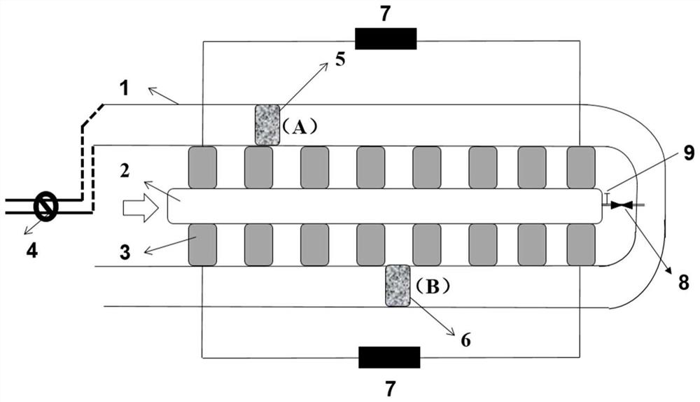
[0034] The side view of the structure of thermochemical reaction thermoelectric power generation device is as follows figure 1 As shown, it mainly includes a U-shaped waste heat fluid channel 1, a cooling water channel 2, a semiconductor thermoelectric module 3, an endothermic reactor 5, an exothermic reactor 6, a fluid flow control valve 4, an accumulator 7, a micro nozzle 8 and a nozzle Pipe control valve 9.

[0035] The U-shaped waste heat fluid channel includes a thermal fluid inlet channel and a thermal fluid outlet channel. The endothermic reactor is arranged on the thermal fluid inlet channel of the U-shaped waste heat fluid channel, and the exothermic reactor is arranged on the thermal fluid of the U-shaped waste heat fluid channel. Exit channel;

[0036] The cooling water channel is arranged on the two side channels of the U-shaped waste heat fluid channel, that is, the middle part of the hot fluid inlet section channel and the hot fluid outlet section channel;

[003...

no. 2 example

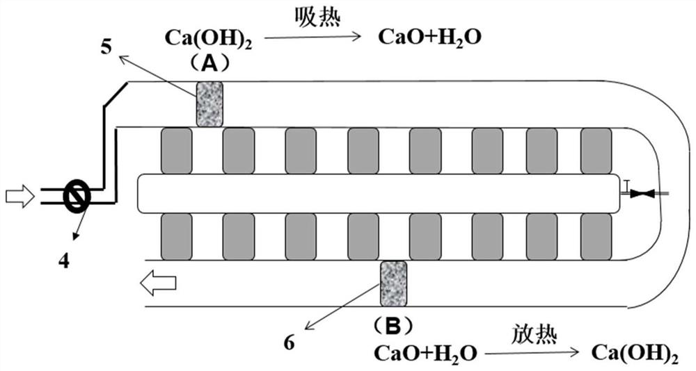
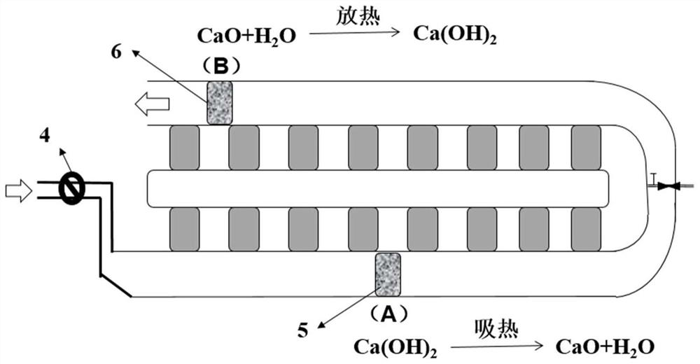
[0050] by chemical reaction As an example to illustrate the thermochemical energy storage process, a working cycle can be divided into two stages, and enters the first stage at the beginning of work, such as figure 2 As shown, the fluid flow direction control valve 4 is opened in the forward direction, and the chemical energy storage substance A in the endothermic reactor 5 is Ca(OH) 2 , the chemical energy storage substance B in the exothermic reactor 6 is CaO; the waste heat fluid flows through the U-shaped waste heat fluid channel 1, and first flows through the chemical energy storage substance Ca(OH) built in the endothermic reactor 5 2 , Ca(OH) 2 An endothermic reaction occurs at high temperature, it begins to convert into CaO, and a certain amount of water vapor is generated, that is, the reaction Ca(OH) 2 →CaO+H 2 O, the temperature of the fluid is lowered after absorbing heat; after that, the waste heat fluid flows through the chemical energy storage material CaO ...


PUM


Abstract

The invention discloses a thermoelectric power generation device utilizing a thermochemical reaction, and belongs to the technical field of waste heat fluid waste heat recycling. The device converts heat energy of waste heat fluid into electric energy by utilizing a semiconductor seebeck effect, and realizes on-way temperature change by utilizing the thermochemical reaction of a thermochemical energy storage substance, thereby reducing the temperature gradient of the hot end temperature of the semiconductor thermoelectric module in the fluid flowing direction; the temperature gradient is maintained near the optimal working temperature domain of the thermoelectric material, efficient matching between the thermoelectric material and the working temperature is achieved, and the system energyefficiency is improved. According to the invention, the thermochemical energy storage technology and the semiconductor thermoelectric power generation technology are combined organically, so the energy efficiency of the thermoelectric conversion system can be improved.

Description

technical field [0001] The invention belongs to the technical field of waste heat recovery and utilization of high-temperature waste heat fluid, and in particular relates to a thermochemical reaction thermoelectric power generation device. Background technique [0002] Thermoelectric power generation is a green and environmentally friendly power generation method that uses the temperature difference between high and low temperature heat sources to generate electricity. The semiconductor thermoelectric generator has the advantages of no noise, no pollution, no wear, small size, light weight, long service life, etc. It shows a good development prospect when it is applied to waste heat energy recovery and utilization technology. However, due to the low thermoelectric conversion efficiency of existing thermoelectric power generation systems, large-scale commercial applications have not yet been realized. Among them, the inefficient matching between the performance of thermoelec...

Claims


Application Information

Patent Timeline
Patent Type & Authority Applications(China)
IPC IPC(8): H02N11/00
CPCH02N11/002
Inventor 何为石颖郭瑞黄颖杨添会
Owner TIANJIN UNIV OF COMMERCE
Why Eureka
Try Eureka