Pesticide spraying equipment for soil treatment

A soil treatment and insecticide technology, applied in the field of soil treatment, can solve problems such as fatigue, reduced efficiency of insecticide, and influence on insecticide effect

Inactive Publication Date: 2020-11-13
陈俊林
View PDF6 Cites 0 Cited by
  • Summary
  • Abstract
  • Description
  • Claims
  • Application Information

AI Technical Summary

Problems solved by technology

[0004] In order to overcome the fact that planters carry sprayers on their backs to carry out insecticide on the soil, it is easy to feel tired, which leads to a decrease in the efficiency of insecticide, and in the process of spraying insecticides, the active ingredients in the insecticides will be deposited in the sprayers, resulting in The shortcoming that affects the disinfestation effect, the technical problem to be solved is: provide a kind of efficient and can stir insecticide when disinsection to soil, can prevent the active ingredient of insecticide from settling at the bottom of the container for soil treatment. Insect Spraying Equipment

Method used


Image

  • Pesticide spraying equipment for soil treatment
  • Pesticide spraying equipment for soil treatment
  • Pesticide spraying equipment for soil treatment

Examples


Embodiment 1

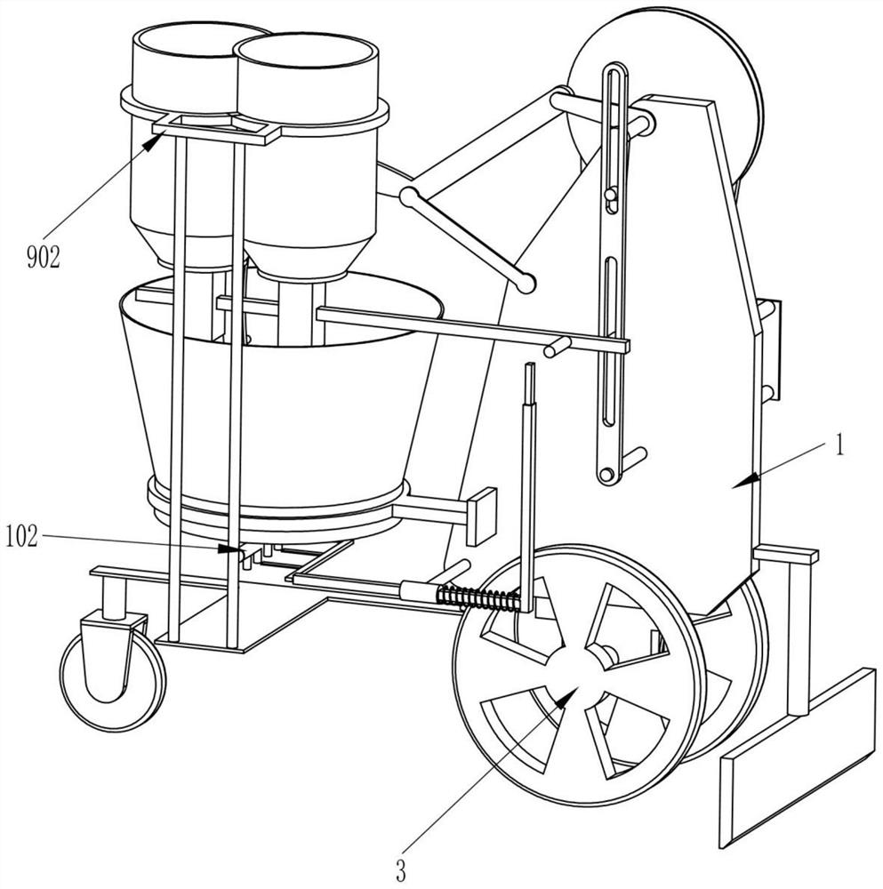
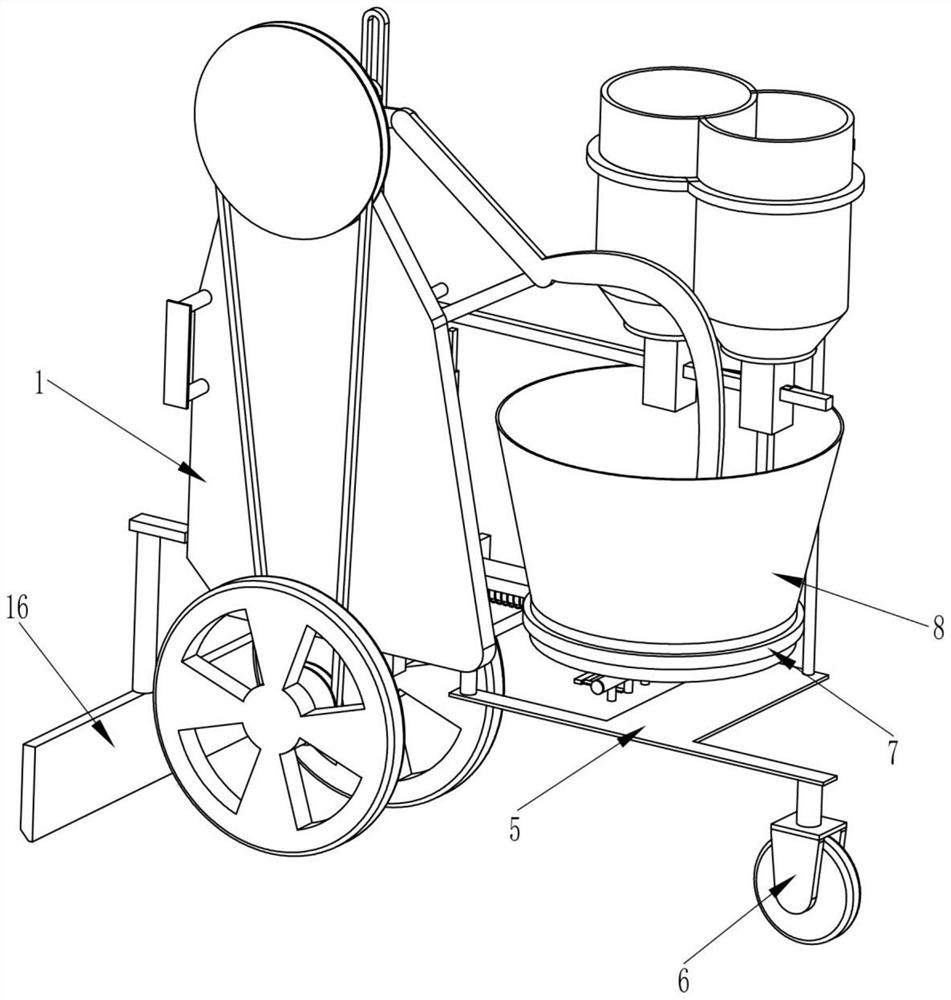
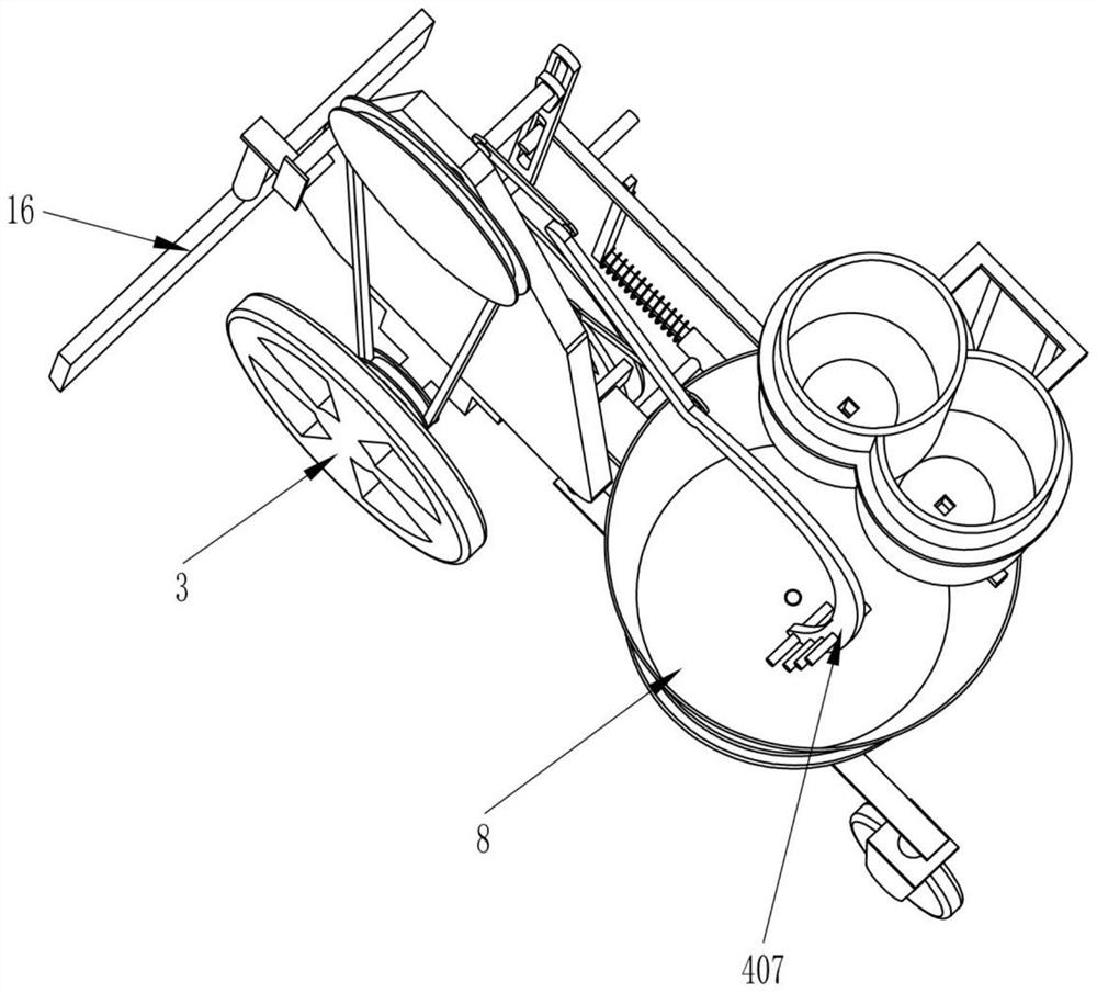
[0022] An insecticide spraying device for soil treatment, such as Figure 1-6 As shown, it includes a mounting plate 1, a handle 101, a drain pipe 102, a transmission shaft 2, a roller 3, an insecticide dilution stirring mechanism 4, a T-shaped plate 5, a wheel base 6, a support frame 7, a stirring frame 8 and Intermittent liquid supply mechanism 9, a handle 101 is installed on one side of the vertically arranged mounting plate 1, a transmission shaft 2 is installed on the mounting plate 1 through a bearing, and the two rollers 3 are installed on both sides of the transmission shaft 2 respectively. end, the insecticide dilution stirring mechanism 4 that can stir the insecticide is installed on the installation plate 1 and the transmission shaft 2, one end of the T-shaped plate 5 is installed on the lower end of the installation plate 1, and the wheel base 6 is fixedly installed on the The other end of the T-shaped plate 5, the supporting frame 7 that plays a supporting role is...

Embodiment 2

[0027]On the basis of Embodiment 1, such as Figure 1-6 As shown, a control blanking mechanism is also included, and the control blanking mechanism includes a guide frame 10, a sliding frame 11, a liquid baffle 12, a telescopic rod 13, a compression spring 14 and a push rod 15, and the guide frame 10 passes through The way of welding is fixedly installed on the side surface of the mounting plate 1, the sliding frame 11 is slidably installed on the guide frame 10, the sliding frame 11 can move left and right along the guide frame 10, and the liquid baffle plate 12 is fixedly installed on the One end of the sliding frame 11, the telescopic rod 13 is fixedly installed on the other end of the sliding frame 11, the compression spring 14 capable of resetting the sliding frame 11 is connected between the guide frame 10 and one end of the telescopic rod 13 and the sliding frame 11 passes through the compressed The spring 14, the push rod 15 is fixedly installed on the slotted rod 905 ...


PUM


Abstract

The invention relates to the technical field of soil treatment, and in particular relates to pesticide spraying equipment for soil treatment. The technical problem to be solved is to provide the pesticide spraying equipment for soil treatment, which is high in efficiency, capable of stirring a pesticide in the process of soil pest control, and capable of preventing effective components of the pesticide from precipitating at the bottom of a container. The pesticide spraying equipment for soil treatment comprises an installation plate, a handle, a drainage pipe, a transmission shaft, idler wheels, a pesticide diluting and stirring mechanism and the like; the handle is installed on one side surface of the installation plate; the transmission shaft is installed on the installation plate through a bearing; and the two idler wheels are respectively installed at two ends of the transmission shaft. When the idler wheels move, a stirring bracket in the invention can continuously stir the pesticide in a stirring frame in a reciprocating manner; the effective components in the pesticide can be prevented from being precipitated; and the pesticide is facilitated to kill pests in soil.

Description

technical field [0001] The invention relates to the technical field of soil treatment, in particular to an insecticide spraying device for soil treatment. Background technique [0002] During spring plowing, the soil needs to be treated with insecticide to prevent the pests in the soil from causing harm to the crops, fruits and vegetables or other plants planted on the soil. The existing method of disinfestation of the soil is generally that the planters use a sprayer Spray diluted pesticides on the soil to achieve the purpose of killing pests in the soil. [0003] Existing methods of disinfestation of soil require planters to carry sprayers filled with insecticides on their backs to carry out insecticides on the soil, and planters carry sprayers on their backs to carry out insecticides on the soil, which makes it easy to feel tired, which leads to a decrease in the efficiency of disinsection reduce, and in the process of spraying insecticides, the active ingredients in the...

Claims


Application Information

Patent Timeline
IPC IPC(8): A01M17/00
CPCA01M17/002
Inventor 陈俊林
Owner 陈俊林
Why Eureka
Try Eureka