Cutting device used for production of aluminum alloy windows
A cutting device, aluminum alloy technology, applied in the direction of positioning device, metal processing equipment, metal processing machinery parts, etc., can solve the problems of production efficiency reduction, cutting material deviation, poor cutting effect, etc., so as to facilitate cutting and improve efficiency Effect
- Summary
- Abstract
- Description
- Claims
- Application Information
AI Technical Summary
Problems solved by technology
Method used
Image

Examples
Embodiment 1
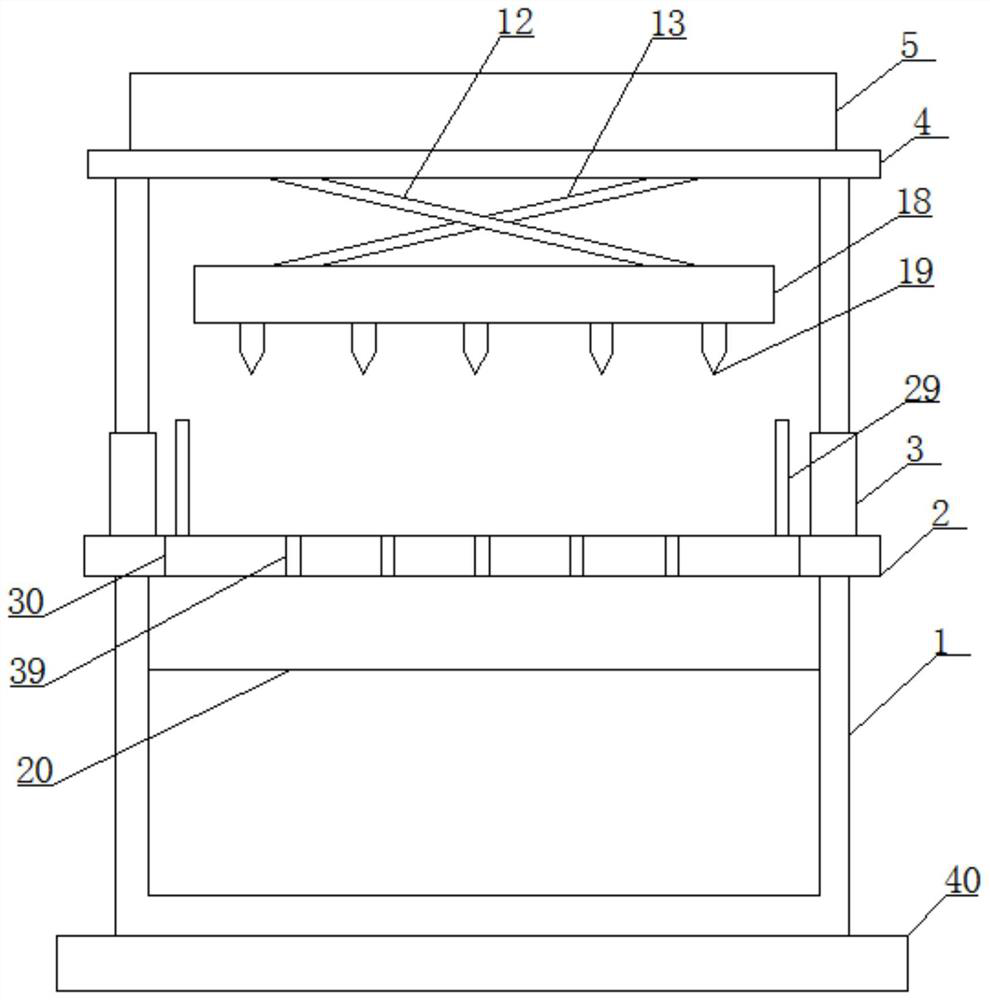
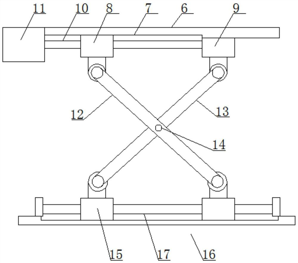
[0032] like Figure 1-4 As shown, the cutting device for the production of aluminum alloy windows according to the embodiment of the present invention includes a base 1 and a processing table 2 located at the top of the base 1, and symmetrically arranged on both sides of the top of the processing table 2. Support 3, the top of described support 3 is provided with crossbeam 4, and described crossbeam 4 is provided with housing 5, and the top in described housing 5 is provided with horizontal plate-6, and the bottom end of described horizontal plate-6 opens There is a chute 7, the bottom end of the chute 7 is provided with a slide block 8 matched thereto, one side of the chute 7 and the bottom end of the horizontal plate one 6 is provided with a fixed block 9, the One side of the fixed block 9 is provided with a screw mandrel 10 passing through the slider 8, and one side of the screw mandrel 10 is connected to the output end of the rotating motor 11 positioned on the horizontal ...
Embodiment 2
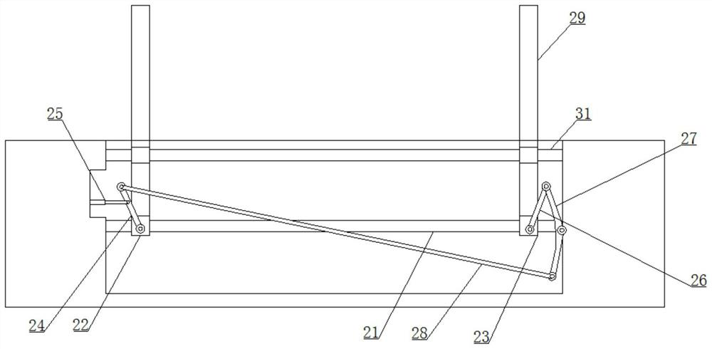
[0035] like Figure 1-4As shown, the chassis 20 is provided with a cross bar 31 passing through the clip 29, the clip 29 is horizontally arranged, and the clip 29 is provided with a hole matching the cross bar 31 The connecting rod 28 is connected to the arc rod 27 and the movable rod 1 24 respectively through the connecting shaft 1, and the sliding rod 17 is a U-shaped structure, and the top of the horizontal plate 2 16 is provided with A slide rail matched with the moving block 15, and the casing 18 is connected to the second horizontal plate 16 through fixing bolts, and the first support rod 12 and the second support rod 13 are respectively passed through the second connecting shaft The corresponding ones are connected with the sliding block 8 , the fixed block 9 and the moving block 15 . It is not difficult to see from the above-mentioned design that the design of the cross bar 31 can limit the movement of the clip 29, so that it is in a smooth state during the movement; ...
Embodiment 3
[0037] like Figure 1-4 As shown, the transmission mechanism includes a rotating shaft 1 32, a rotating shaft 2 33 and a rotating shaft 3 34 arranged sequentially from top to bottom in the casing 18, the rotating shaft 1 32, the rotating shaft 2 33 The cutting knife 19 matched with it is symmetrically arranged on the rotating shaft three 34, one side of the rotating shaft one 32 is connected with the output end of the drive motor located in the casing 18, and the rotating shaft One 32 is sleeved with a belt one 35 connected to the second rotating shaft 33, and the second rotating shaft 33 is symmetrically provided with a second belt 36 connected to the third rotating shaft 34, and the first rotating shaft 32 and the second rotating shaft 33 are provided with a pulley one 37 matched with the belt one 35, and the second belt 36 is respectively connected with the second rotating shaft 33 and the third rotating shaft 34 through the second pulley 38 . It is not difficult to see f...
PUM
 Abstract
Description
Claims
Application Information
 - R&D
- Intellectual Property
- Life Sciences
- Materials
- Tech Scout
- Unparalleled Data Quality
- Higher Quality Content
- 60% Fewer Hallucinations
Browse by: Latest US Patents, China's latest patents, Technical Efficacy Thesaurus, Application Domain, Technology Topic, Popular Technical Reports.
© 2025 PatSnap. All rights reserved.Legal|Privacy policy|Modern Slavery Act Transparency Statement|Sitemap|About US| Contact US: help@patsnap.com